
Elements Of Electromagnetics
7th Edition
ISBN: 9780190698614
Author: Sadiku, Matthew N. O.
Publisher: Oxford University Press
expand_more
expand_more
format_list_bulleted
Related questions
Concept explainers
Question
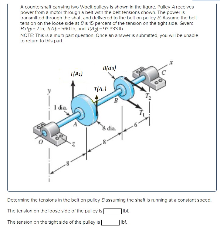

Transcribed Image Text:A countershaft carrying two V-belt pulleys is shown in the figure. Pulley A receives
power from a motor through a belt with the belt tensions shown. The power is
transmitted through the shaft and delivered to the belt on pulley B. Assume the belt
tension on the loose side at Bis 15 percent of the tension on the tight side. Given:
B(dg) = 7 in, T(A) = 560 lb, and TA) = 93.333 lb.
NOTE: This is a multi-part question. Once an answer is submitted, you will be unable
to return to this part.
B(dB)
T(A1)
T(A2)
1 dia.
8 dia.
Determine the tensions in the belt on pulley Bassuming the shaft is running at a constant speed.
The tension on the loose side of the pulley is
| Ibf.
The tension on the tight side of the pulley is
Ibf.
Expert Solution
This question has been solved!
Explore an expertly crafted, step-by-step solution for a thorough understanding of key concepts.

This is a popular solution

Trending nowThis is a popular solution!

Step by stepSolved in 2 steps

Knowledge Booster


Learn more about
Need a deep-dive on the concept behind this application? Look no further. Learn more about this topic, mechanical-engineering and related others by exploring similar questions and additional content below.Similar questions
- An axle is composed of elements laid by S355 E-module 2.1x10⁵ N/mm2, transverse contraction factor 0.3. As shown in the picture, we have on the right side two forces of 10,000 N whichshows at an angle 15 upwards and forms a moment which is statically compensated by the force F2 on the left side. The shaft is stored in positions A and B. In the same position (for the sake of simplicity) there are two critical cross-sections that lead to stress concentrations.v) Determine b nom which is necessary to transfer the torque you have calculated when the coefficient of friction is 0.3. Comment on the result when you compare b real and b nom.vi) Determine G max.vii) Does the sleeve withstand the stresses when the permissible stress is 355 N/mm2?arrow_forwardA countershaft carrying two V-belt pulley is shown in Figure 1. Pulley A receivespower from a motor through a belt with the belt tensions shown. The power is transmittedthrough the shaft and delivered to the belt on Pulley B. Assume the belt tension on the loose sideat B is 15 percent of the tension on the tight side.(a) Determine the tensions in the belt on pulley B (assuming the shaft is running at a constantspeed).(b) Find the magnitudes of the bearing reaction forces assuming the bearings act as simplesupports.(c) Draw the shear force and bending moment diagrams for the shaft.arrow_forwardPravinbhaiarrow_forward
- For two existing torques, what third force at a given distance from the pivot will balance them? Imagine a meter stick set up as in the figure. It hangs from a central bracket, and two hanging masses can hang from it from each of their brackets. At a third location, a force probe can either pull up or pull down on the stick, depending on what is needed to balance the stick. The mass of the meter stick is 120 g. sketch the situation (drawing r1, r2, r3, F1, F2, and F3) and determine the magnitude (value) and direction (+ or -) of each torque. Don't include the mass of a bracket that would hold the hanging mass in place; assume the mass listed is the entire mass hanging at that point. For each trial, use the principle of equilibrium (where the sum of torques is zero) to calculate the third, unknown force acting at x3arrow_forwardFor two existing torques, what third force at a given distance from the pivot will balance them? Imagine a meter stick set up as in the figure. It hangs from a central bracket, and two hanging masses can hang from it from each of their brackets. At a third location, a force probe can either pull up or pull down on the stick, depending on what is needed to balance the stick. The mass of the meter stick is 120 g. sketch the situation (drawing r1, r2, r3, F1, F2, and F3) and determine the magnitude (value) and direction (+ or -) of each torque. Don't include the mass of a bracket that would hold the hanging mass in place; assume the mass listed is the entire mass hanging at that point. For each trial, use the principle of equilibrium (where the sum of torques is zero) to calculate the third, unknown force acting at x3arrow_forwardFor two existing torques, what third force at a given distance from the pivot will balance them? Imagine a meter stick set up as in the figure. It hangs from a central bracket, and two hanging masses can hang from it from each of their brackets. At a third location, a force probe can either pull up or pull down on the stick, depending on what is needed to balance the stick. The mass of the meter stick is 120 g. sketch the situation (drawing r1, r2, r3, F1, F2, and F3) and determine the magnitude (value) and direction (+ or -) of each torque. Don't include the mass of a bracket that would hold the hanging mass in place; assume the mass listed is the entire mass hanging at that point. For each trial, use the principle of equilibrium (where the sum of torques is zero) to calculate the third, unknown force acting at x3arrow_forward
- Assume if the shear stress in steel exceeds about 4.00 x 10⁸ N/m² the steel ruptures. .(a)..Determine the shearing force necessary to shear a steel bolt 1.05 cm in diameter. Enter a number. differs significantly from the correct answer. Rework your solution from the beginning and check each step carefully. N (b) Determine the shearing force necessary to punch a 2.00-cm-diameter hole in a steel plate 0.410 cm thick. Narrow_forwardA crank shaft is operated as shown in the figure. A load F1 = 9.73 N is applied and the operator %3D dz applies a load P to counter. The system is in equilibrium and all of the bearings are perfectly dz aligned such that they do not produce moments on the rotating crank. The geometry is given by, w = 7.31 [m), dl = 9.69 m], d2 = 7.57 m). 6.14 (m), d5 = 3.7 (m), %3D d1 d3 = 9.87 (m), d4 %3D F2 and h1 4.4 (m), find the following: %3D F1 Part 1. Express the reaction forces exerted on the bar by the journal bearing at point B. Use the coordinate system shown in the diagram 10 5% 100% Submit [N] Part 2. Express the reaction forces exerted on the bar by the journal bearing at Point A. Use the coordinate system shown in the diagram. 5% 100% 10 Submit [N]arrow_forwardDetermination of vertical displacement of Mid-Term Project pipe assembly Find the vertical displacement at position C in the figure. 800 mm Pipe inner diameter: 40 mm, Pipe outer diameter: 60 mm Material: A-36 Steel 600 N B. -By the force 600N, the AB part of the pipe is subjected to bending and torsional loads. BC part is subjected to bending load. -The energy equation by this load is as follows. Energy equation by torsional load: 400 mm T²dx (U), = 2GJ Problem: Energy equation by bending load a) First, draw a free body diagram and the AB part Of the bending/torsional load of the BC and Derive the bending load equation. So M²dx (U) = 2EI By applying it to the high energy formula, Save energy and make it the same as external energy Release to find the vertical displacement. -The sum of the internal energy of 2 energy is as follows. U=U: +Ub b) Creo modeling and structural analysis -Due to energy conservation, the sum of the internal energy U is the external due to the load 600 NGet the…arrow_forward
arrow_back_ios
arrow_forward_ios
Recommended textbooks for you
- Elements Of ElectromagneticsMechanical EngineeringISBN:9780190698614Author:Sadiku, Matthew N. O.Publisher:Oxford University Press
 Mechanics of Materials (10th Edition)Mechanical EngineeringISBN:9780134319650Author:Russell C. HibbelerPublisher:PEARSON
 Thermodynamics: An Engineering ApproachMechanical EngineeringISBN:9781259822674Author:Yunus A. Cengel Dr., Michael A. BolesPublisher:McGraw-Hill Education
  Control Systems EngineeringMechanical EngineeringISBN:9781118170519Author:Norman S. NisePublisher:WILEY
 Mechanics of Materials (MindTap Course List)Mechanical EngineeringISBN:9781337093347Author:Barry J. Goodno, James M. GerePublisher:Cengage Learning
 Engineering Mechanics: StaticsMechanical EngineeringISBN:9781118807330Author:James L. Meriam, L. G. Kraige, J. N. BoltonPublisher:WILEY
Elements Of Electromagnetics
Mechanical Engineering
ISBN:9780190698614
Author:Sadiku, Matthew N. O.
Publisher:Oxford University Press
Mechanics of Materials (10th Edition)
Mechanical Engineering
ISBN:9780134319650
Author:Russell C. Hibbeler
Publisher:PEARSON
Thermodynamics: An Engineering Approach
Mechanical Engineering
ISBN:9781259822674
Author:Yunus A. Cengel Dr., Michael A. Boles
Publisher:McGraw-Hill Education
Control Systems Engineering
Mechanical Engineering
ISBN:9781118170519
Author:Norman S. Nise
Publisher:WILEY
Mechanics of Materials (MindTap Course List)
Mechanical Engineering
ISBN:9781337093347
Author:Barry J. Goodno, James M. Gere
Publisher:Cengage Learning
Engineering Mechanics: Statics
Mechanical Engineering
ISBN:9781118807330
Author:James L. Meriam, L. G. Kraige, J. N. Bolton
Publisher:WILEY