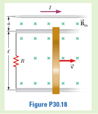
You are working in a laboratory that uses motional emf to make magnetic measurements. You have found that it is difficult to create a uniform magnetic field across the entire sliding-bar apparatus shown in 30.8a, with a resistance R connected between the rails. You decide to investigate creating the magnetic field with a long, straight, current- carrying conductor lying next to and parallel to one of the rails, as shown in P30.18. This will create a nonuniform field across the plane of the bar and rails. You set up the apparatus in this way, with the current-carrying wire a distance a from the upper rail. You wish to find an expression for the force necessary to slide the bar at a constant speed of υ to the right in P30.18 if the wire carries a current I. (Hint: Two separate integrations will be required.)


Trending nowThis is a popular solution!
Step by stepSolved in 2 steps with 4 images

- As a diligent physics student, you carry out physics experiments at every opportunity. At this opportunity, you carry a 1.15 m long rod as you jog at 3.17 m/s, holding the rod perpendicular to your direction of motion. What is the magnitude B of the magnetic field that is perpendicular to both the rod and your direction of motion and that induces an EMF of 0.287 mV across the rod? Express the answer in milliteslas. B = mTarrow_forwardQ. Consider the configuration shown on the right, the inner cylindrical conductor of radius 'a' surrounded by a cylindrical shell of inner radius 'b' and outer radius 'c'. The inner conductor and the outer shell each carry equal and opposite currents I. Where I is uniformly distributed through the conductors. a I a) Find the magnetic field intensity for r< a and aarrow_forwardA circular loop of wire lies in a plane perpendicular to a magnetic field. The magnetic field has a magnitude of 1.3 T and points out of the page as shown in the figure. The radius of the loop is 18 cm and it has a resistance of 3.2 Ω. Find the induced emf in the loop of wire if the magnetic field doubles in magnitude in 1 seconds. What is the induced current in the loop? In which direction is the induced current?arrow_forwardStill think that unit conversion isn't important? Here is a widely publicized, true story about how failing to convert units resulted in a huge loss. In 1998, the Mars Climate Orbiter probe crashed into the surface of Mars, instead of entering orbit. The resulting inguiry revealed that NASA navigators had been making minor course corrections in SI units, whereas the software written by the probe's makers implicitly used British units. In the United States, most scientists use Sl units, whereas most engineers use the British, or Imperial, system of units. (Interestingly, British units are not used in Britain.) For these two groups to be able to communicate to one another, unit conversions are necessary. The unit of force in the SI system is the newton (N), which is defined in terms of basic Sl units as 1 N=1 kg · m/s?. The unit of force in the British system is the pound (lb), which is defined in terms of the slug (British unit of mass), foot (ft), and second (s) as 1 lb =1 slug ·…arrow_forwardThree loops of wire move near a long straight wire carrying a current as in Figure P20.9. What is the direction of the induced current, if any, in (a) loop A, (b) loop B, and (c) loop C. A B I C Figure P20.9arrow_forwardAs a diligent physics student, you carry out physics experiments at every opportunity. At this opportunity, you carry a 1.33 m long rod as you jog at 3.25 m/s, holding the rod perpendicular to your direction of motion. What is the magnitude B of the magnetic field that is perpendicular to both the rod and your direction of motion and that induces an EMF of 0.283 mV across the rod? Express the answer in milliteslas. B = mTarrow_forwardA 35.6-meter-long spacecraft flies past a neutron star, and passes through the neutron star s extremely powerful magnetic field of strength 7.95 x 10^4 T. The spacecraft travels at a velocity of 2.43 km/s in a direction perpendicular to the magnetic field; the spacecraft s long axis is also perpendicular to the magnetic field. What is the induced emf (voltage) between the two ends of the spacecraft? 6.88E+08 V 6.88E+09 V 6.88E+06 V 6.88E+05 Varrow_forwardIn the figure below, the two ends of a U-shaped wire of mass m = 7.00 g and length L = 17.0 cm are immersed in mercury (which is a conductor). The wire is in a uniform field of magnitude B = 0.0860 T. A switch (unshown) is rapidly closed and then reopened, sending a pulse of current through the wire, which causes the wire to jump upward. If jump height h = 4.00 m, how much charge was in the pulse? Assume that the duration of the pulse is much less than the time of flight. Hg. Number i X L X Units X Marrow_forwardarrow_back_iosarrow_forward_ios
 College PhysicsPhysicsISBN:9781305952300Author:Raymond A. Serway, Chris VuillePublisher:Cengage Learning
 University Physics (14th Edition)PhysicsISBN:9780133969290Author:Hugh D. Young, Roger A. FreedmanPublisher:PEARSON
 Introduction To Quantum MechanicsPhysicsISBN:9781107189638Author:Griffiths, David J., Schroeter, Darrell F.Publisher:Cambridge University Press
 Physics for Scientists and EngineersPhysicsISBN:9781337553278Author:Raymond A. Serway, John W. JewettPublisher:Cengage Learning
 Lecture- Tutorials for Introductory AstronomyPhysicsISBN:9780321820464Author:Edward E. Prather, Tim P. Slater, Jeff P. Adams, Gina BrissendenPublisher:Addison-Wesley
 College Physics: A Strategic Approach (4th Editio...PhysicsISBN:9780134609034Author:Randall D. Knight (Professor Emeritus), Brian Jones, Stuart FieldPublisher:PEARSON


