Concept explainers
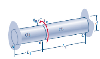
A composite shaft with a total length L, where L = L1 + L2, is created by connecting two shafts of equal diameter (d) at joint B. The shaft segment AB is characterized by a shear modulus G1, while segment BC has a shear modulus G2. An external torque Tg is applied at joint B, and the ends A and C are immobilized to prevent rotation.
(a) Using Displacement Method, determine a formula for os, which represents the angle of rotation at joint B.
(b) Calculate expressions for T1 and T2, representing the internal torques in segments AB and BC, respectively.
(c) Find the maximum shear stress in each segment. Express all responses in terms of the given torque Ty and the physical parameters of the composite shaft: d, G1, G2, L1, and L2.

Trending nowThis is a popular solution!
Step by stepSolved in 8 steps with 8 images

- I need a and b both answers typingarrow_forwardPart 2,3,4arrow_forwardA bronze pipe (1) is to be connected to an aluminum alloy pipe (2) at flange B. When put in place, however, a gap of A = 0.35 in. exists between the two pipes. Bronze pipe (1) has an elastic modulus of E1 = 16,000 ksi, a cross-sectional area of A1 = 2.66 in.?, and a length of L1 = 6.7 ft. Aluminum alloy pipe (2) has an elastic modulus of E2 = 10,000 ksi, a cross-sectional area of A2 = 1.37 in.2, and a length of L2 = 10.2 ft. If bolts are inserted in the flanges and tightened so that the gap at B is closed, determine: (a) the normal stresses produced in each of the members. (b) the final position of flange B with respect to support A. L2 В (1) Answer: (a) 01 = ksi 02 = ksi (b) ÕB/A = in.arrow_forward
- SOLVES STEP BY STEP, USE TABLE IF NECESSARYarrow_forwardA thin polymer plate PQR is deformed so that corner Q is displaced downward 0.9 mm to new position Q', as shown in. Determine the shear strain at Q' associated with the two edges (PQ and QR). Assume a = 150 mm, b = 216 mm, c = 180 mm, and A = 0.9 mm. a b P R C Answer: Shear strain y = Q i A X urad.arrow_forwardPlease show all steps so your process is easy to followarrow_forward

 Structural Analysis (10th Edition)Civil EngineeringISBN:9780134610672Author:Russell C. HibbelerPublisher:PEARSON
 Principles of Foundation Engineering (MindTap Cou...Civil EngineeringISBN:9781337705028Author:Braja M. Das, Nagaratnam SivakuganPublisher:Cengage Learning
 Fundamentals of Structural AnalysisCivil EngineeringISBN:9780073398006Author:Kenneth M. Leet Emeritus, Chia-Ming Uang, Joel LanningPublisher:McGraw-Hill Education
 Traffic and Highway EngineeringCivil EngineeringISBN:9781305156241Author:Garber, Nicholas J.Publisher:Cengage Learning


