
Elements Of Electromagnetics
7th Edition
ISBN: 9780190698614
Author: Sadiku, Matthew N. O.
Publisher: Oxford University Press
expand_more
expand_more
format_list_bulleted
Related questions
Concept explainers
Question
thumb_up100%
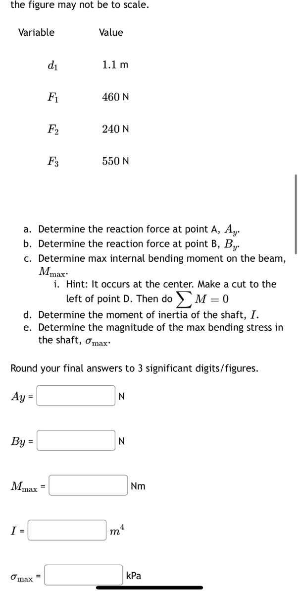

Transcribed Image Text:the figure may not be to scale.
Variable
By =
Mmax =
d₁
I =
F₁
max
F₂
F3
Value
1.1 m
a. Determine the reaction force at point A, A.
b. Determine the reaction force at point B, B.
c. Determine max internal bending moment on the beam,
460 N
Mmax
i. Hint: It occurs at the center. Make a cut to the
left of point D. Then do M = 0
d. Determine the moment of inertia of the shaft, I.
e. Determine the magnitude of the max bending stress in
the shaft, max.
Round your final answers to 3 significant digits/figures.
Ay =
240 N
550 N
N
N
ma
Nm
kPa

Transcribed Image Text:10:59 A
A circular steel shaft has a radius of 0.05 m. The shaft is
supported by rollers at A and B.
F₁
F₂
JIL
D
d₁
Variable
d₁
F₁
F₂
d₁
F3
Values for the figure are given in the following table. Note
the figure may not be to scale.
Value
1.1 m
wamap.org
460 N
240 N
550 N
d₁
F3
E
d₁
B
a. Determine the reaction force at point A, Ay.
b. Determine the reaction force at point B, By.
c. Determine max internal bending moment on the beam,
Mmax:
i. Hint: It occurs at the center. Make a cut to the
left of point D. Then doΣM = 0
d. Determine the moment of inertia of the shaft, I.
e. Determine the magnitude of the max bending stress in
the shaft, max
Expert Solution
This question has been solved!
Explore an expertly crafted, step-by-step solution for a thorough understanding of key concepts.

Step by stepSolved in 4 steps with 3 images

Knowledge Booster


Learn more about
Need a deep-dive on the concept behind this application? Look no further. Learn more about this topic, mechanical-engineering and related others by exploring similar questions and additional content below.Similar questions
- A992 steel bar is subjected to the loading shown. If the cross-sectional area of the bar is 80 mm², determine the displacement of C and D.arrow_forwardThe figure below depicts the tire, axle, and gear of a large tractor. The entire structure is in mechanical equilibrium. Bearings support the rotating axle at points A and C attached to the tractor's frame. A force FD = 5000 lb is applied in the -z direction at point G of a gear with a 3-in radius. The force W = 1000 lb in the +z direction represents a normal force resulting from the weight of the tractor. The force Q acting in the +x direction, represents the traction force between the tire and the ground. The wheel, axle, and gear assembly weigh 150 lb with center of gravity at point D, which lies on the y axis with coordinate yp = -18 in. Points A, C, D (not seen in the figure), and E lie in the yz plane. Point G lies in the xy plane. Questions & Analysis: (a) Draw the FBD for the wheel, axle, and gear assembly if the bearings at A and B resist moments and the bearing at A is a thrust bearing. Label all unknowns. (b) Is the assembly statically determinate or statically…arrow_forwardThe device is used to measure a change in temperature. Bars AB and CD are made of A-36 steel and 2014-T6 aluminum alloy respectively. When the temperature is at 65° F, ACE is in the horizontal position. Figure 1.5 in. -0.25 in. C 3 in. 1 of 1 اساساسا Part A Determine the vertical displacement of the pointer at E when the temperature rises to 160 ° F. (Figure 1) Express your answer with the appropriate units. SE = Value Submit Request Answer Provide Feedback Units ?arrow_forward
- A stress element in a rock mass making up a slope experiences a 2D stress as follows: σx = 8 MPa, σy = 4 MPa , tauxy = 3 MPa a. Draw the Mohr circle. On Mohr's circle, mark the location of the x and y planes, mark the angle of rotation θ from the x plane to the σ₁,σ3,and taumax plane. Prove that the angle of rotation of the Mohr circle is 2 times the angle of rotation of the element. b. Write down the coordinates of the center of Mohr's circle and calculate its radius.arrow_forwardThe baloon is in balance with 3 ropes. If each of the rope can stand to 500N tensile force, find the minimum F force that the ropes will not broke.arrow_forward2-96 Instead of representing each force in Cartesian notation, use the dot product to determine the angle between one of the following pairs: FB and FC FB and member ADarrow_forward
arrow_back_ios
arrow_forward_ios
Recommended textbooks for you
- Elements Of ElectromagneticsMechanical EngineeringISBN:9780190698614Author:Sadiku, Matthew N. O.Publisher:Oxford University Press
 Mechanics of Materials (10th Edition)Mechanical EngineeringISBN:9780134319650Author:Russell C. HibbelerPublisher:PEARSON
 Thermodynamics: An Engineering ApproachMechanical EngineeringISBN:9781259822674Author:Yunus A. Cengel Dr., Michael A. BolesPublisher:McGraw-Hill Education
  Control Systems EngineeringMechanical EngineeringISBN:9781118170519Author:Norman S. NisePublisher:WILEY
 Mechanics of Materials (MindTap Course List)Mechanical EngineeringISBN:9781337093347Author:Barry J. Goodno, James M. GerePublisher:Cengage Learning
 Engineering Mechanics: StaticsMechanical EngineeringISBN:9781118807330Author:James L. Meriam, L. G. Kraige, J. N. BoltonPublisher:WILEY
Elements Of Electromagnetics
Mechanical Engineering
ISBN:9780190698614
Author:Sadiku, Matthew N. O.
Publisher:Oxford University Press
Mechanics of Materials (10th Edition)
Mechanical Engineering
ISBN:9780134319650
Author:Russell C. Hibbeler
Publisher:PEARSON
Thermodynamics: An Engineering Approach
Mechanical Engineering
ISBN:9781259822674
Author:Yunus A. Cengel Dr., Michael A. Boles
Publisher:McGraw-Hill Education
Control Systems Engineering
Mechanical Engineering
ISBN:9781118170519
Author:Norman S. Nise
Publisher:WILEY
Mechanics of Materials (MindTap Course List)
Mechanical Engineering
ISBN:9781337093347
Author:Barry J. Goodno, James M. Gere
Publisher:Cengage Learning
Engineering Mechanics: Statics
Mechanical Engineering
ISBN:9781118807330
Author:James L. Meriam, L. G. Kraige, J. N. Bolton
Publisher:WILEY