Introductory Circuit Analysis (13th Edition)
13th Edition
ISBN: 9780133923605
Author: Robert L. Boylestad
Publisher: PEARSON
expand_more
expand_more
format_list_bulleted
Concept explainers
Question

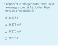
Transcribed Image Text:A capacitor is charged with 150mC and
the energy stored is 1.2 Joules, then
the value of capacitor is
O 8.375 F
O 9.375 mF
O 8.375 mF
O 9.375 F
Expert Solution
This question has been solved!
Explore an expertly crafted, step-by-step solution for a thorough understanding of key concepts.
Step by stepSolved in 2 steps with 1 images

Knowledge Booster
Learn more about
Need a deep-dive on the concept behind this application? Look no further. Learn more about this topic, electrical-engineering and related others by exploring similar questions and additional content below.Similar questions
- Please help plot the voltage waveforms across the capacitor and resistor.arrow_forwarddetermine the equivalent inductance of this circuit belowarrow_forward1. Determine the charge and voltage across each capacitor in the following circuit, assum- ing that the battery has been connected for a long period of time. 6.0 nF 1.0 nF 3.0 nF 5.0 NF 3.0 nF 12.0 V 4.0 nFarrow_forward
- Given the circuit and the input waveform, what is the charge voltage across the capacitor express answer in volts 4" 0 20 V -20 V 64 Vi C 10V + R V 19arrow_forwardFind equivalent inductance at the terminals a and b of the circuit below. *Round off the final answer to the nearest 4 decimal places with unit. Rounding off should only be done on final answer.arrow_forwardAssuming the capacitor is fully charged, what is the voltage across the capacitor 2 seconds after the switch is opened? E=33 V, R1=300 kſ, R2=300 k, C=10 uF R2 R1 ww + 55.2 V None of the above 31.5 V 47.3 V 23.6 V 39.4 V #6 Carrow_forward
- The capacitance of a certain variable capacitor may be varied between limits of 1 × 10-20 F and 5×10⁻¹⁰ F by turning a knob attached to the movable plates. The capacitor is set to 5 × 10⁻¹⁰ F, and is charged by connecting it to a battery of EMF 200 V. What is the charge on the plates? The battery is then disconnected and the capacitance changed to 1 × 10⁻¹⁰ F. Assuming that no charge is lost from the plates, what is now the potential difference between them? How much mechanical work is done against electrical forces in changing the capacitance?arrow_forwardCalculate the total capacitance of the circuits below: C1 15kF C2 C4 10KF 10KF C3 C5 10KF 10KFarrow_forward1arrow_forward
arrow_back_ios
SEE MORE QUESTIONS
arrow_forward_ios
Recommended textbooks for you
 Introductory Circuit Analysis (13th Edition)Electrical EngineeringISBN:9780133923605Author:Robert L. BoylestadPublisher:PEARSON
 Delmar's Standard Textbook Of ElectricityElectrical EngineeringISBN:9781337900348Author:Stephen L. HermanPublisher:Cengage Learning
 Programmable Logic ControllersElectrical EngineeringISBN:9780073373843Author:Frank D. PetruzellaPublisher:McGraw-Hill Education
 Fundamentals of Electric CircuitsElectrical EngineeringISBN:9780078028229Author:Charles K Alexander, Matthew SadikuPublisher:McGraw-Hill Education
 Electric Circuits. (11th Edition)Electrical EngineeringISBN:9780134746968Author:James W. Nilsson, Susan RiedelPublisher:PEARSON
 Engineering ElectromagneticsElectrical EngineeringISBN:9780078028151Author:Hayt, William H. (william Hart), Jr, BUCK, John A.Publisher:Mcgraw-hill Education,

Introductory Circuit Analysis (13th Edition)
Electrical Engineering
ISBN:9780133923605
Author:Robert L. Boylestad
Publisher:PEARSON

Delmar's Standard Textbook Of Electricity
Electrical Engineering
ISBN:9781337900348
Author:Stephen L. Herman
Publisher:Cengage Learning

Programmable Logic Controllers
Electrical Engineering
ISBN:9780073373843
Author:Frank D. Petruzella
Publisher:McGraw-Hill Education

Fundamentals of Electric Circuits
Electrical Engineering
ISBN:9780078028229
Author:Charles K Alexander, Matthew Sadiku
Publisher:McGraw-Hill Education

Electric Circuits. (11th Edition)
Electrical Engineering
ISBN:9780134746968
Author:James W. Nilsson, Susan Riedel
Publisher:PEARSON

Engineering Electromagnetics
Electrical Engineering
ISBN:9780078028151
Author:Hayt, William H. (william Hart), Jr, BUCK, John A.
Publisher:Mcgraw-hill Education,