
Related questions
Concept explainers
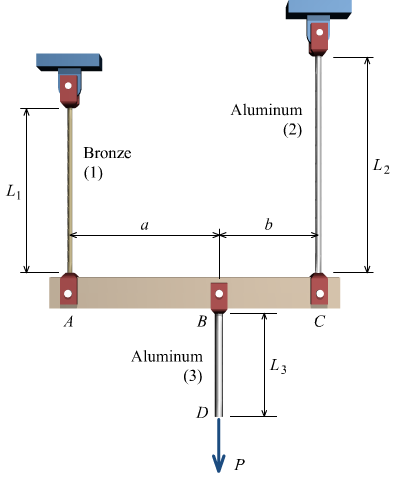
Rigid bar ABC is supported by bronze rod (1) and aluminum rod (2), as shown. A concentrated load P is applied to the free end of aluminum rod (3). Bronze rod (1) has an elastic modulus of E1 = 15,000 ksi and a diameter of d1 = 0.45 in. Aluminum rod (2) has an elastic modulus of E2 = 10,000 ksi and a diameter of d2 = 0.75in. Aluminum rod (3) has a diameter of d3 = 0.95in. The yield strength of the bronze is 48 ksi and the yield strength of the aluminum is 40 ksi. Assume a = 2.5 ft, b = 1.5 ft, L1 = 6 ft, L2 = 8 ft, and L3 = 3 ft.
FIND:
(a) Calculate the cross-sectional areas of the three rods.
(b) For a factor of safety of 1.9, calculate the allowable stresses in the bronze and the aluminum rods.
(c) On a piece of paper, sketch a free body diagram (FBD) cut through rod (3) and also a FBD of the rigid bar. Using these, find a relationship between the force in rod 1 (F1) and the applied load, P, a relationship between the force in rod 2 (F2) and the applied load, P, and also a relationship between the force in rod 3 (F3) and the applied load, P.
(d) Based on the allowable stress for the bronze, calculate the maximum allowable force that can be supported by rod (1), and the corresponding maximum value for the applied load P.
(e) Based on the allowable stress for the aluminum, calculate the maximum allowable force that can be supported by rod (2), and the corresponding maximum value for the applied load P.
(f) Based on the allowable stress for the aluminum, calculate the maximum allowable force that can be supported by rod (3), and the corresponding maximum value for the applied load P.
(g) What is the magnitude of load P that can safely be applied to the structure for a minimum factor of safety of 1.9?
(h) Determine the deformations in rods (1), (2), and (3) when load P equals Pmax from Part 7.
(I) Using the results from Part 8, determine the deflections of Joint B and Point D.
(J) The pin used at B has an ultimate shear strength of 52 ksi. If a factor of safety of 3.4 is required, determine the allowable shear stress in this pin.
(K) The pin used at B is a double shear pin connection. Determine the minimum pin cross-sectional area, and the corresponding minimum pin diameter that can be used at B.


Step by stepSolved in 2 steps with 1 images


- Materials Science And Engineering PropertiesCivil EngineeringISBN:9781111988609Author:Charles GilmorePublisher:Cengage Learning