Structural Analysis
6th Edition
ISBN: 9781337630931
Author: KASSIMALI, Aslam.
Publisher: Cengage,
expand_more
expand_more
format_list_bulleted
Question

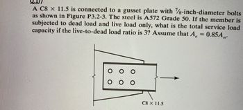
Transcribed Image Text:A C8 x 11.5 is connected to a gusset plate with 7/8-inch-diameter bolts
as shown in Figure P3.2-3. The steel is A572 Grade 50. If the member is
subjected to dead load and live load only, what is the total service load
capacity if the live-to-dead load ratio is 3? Assume that A = 0.85A,,.
C8 × 11.5
Expert Solution
This question has been solved!
Explore an expertly crafted, step-by-step solution for a thorough understanding of key concepts.
This is a popular solution
Trending nowThis is a popular solution!
Step by stepSolved in 5 steps

Knowledge Booster
Learn more about
Need a deep-dive on the concept behind this application? Look no further. Learn more about this topic, civil-engineering and related others by exploring similar questions and additional content below.Similar questions
- A W14X120 is used as a tension member in atruss. The flanges of the member are connected to a gusset plate by 3/4 inch boltas shown below. Use A36 steel with Fy-36 ksi and Fu=58 ksi Determine the Yielding Capacity of the section based on LRFD (kips) Determine the Tensile Rupture capacity of the section based on LRFD Determine the Demand to Governing Capacity Ratio (based on yielding and rupture only) if the Demand load carried by the section are DL=200 kips LL=400 kips use LRFD Properties and Dimension Ag=35.30 in^2 x = 6.24 in ry= 3.74 in d=14.5 in tf=0.94 in bf=14.7 in tw=0.59 in k=1.54 d=14.5 Y k1=1.5 bf=14.7 tf-0.94 X -tw=0.59 Harrow_forwardAnswer the following for the section at Point D Only Calculate the distributed load "w" that: Will cause the section crack Will cause the reinforcement to yield. Material Properties: F'c = 5000 psi Fy = 60000 psi Es = 29000000 psi Ln = 27 ft L wl₂² 16 wl,² 14 CD L wl,2 vl₁² 10 11 win² 16 h: 28 in A=4 in² b=14 in n d: 25 inarrow_forwardThe tension member shown in Figure 3.4-2 is a PL 5/8 x 10, and the steel is A36. The bolts are 7/8-inch in diameter. a. Determine the design strength for LRFD. b. Determine the allowable strength for ASD. | 2" +|+| in seinefrinehich 9 оо SOarrow_forward
- Question 1: (Use NSCP 505.3 provisions and ASEP Steel Handbook for effective length factors) Use AISC Equation E3-2 or E3-3 and determine the nominal axial compressive strength for the following cases: a. L= 15 ft b. L=20 ft W10 × 33 A992 steel FIGURE P4.3-1arrow_forwardFive M20 8.8/ bolts are used in the connection between a beam and a column. Both sides of the cleat plate are welded to column using fillet weld (Manual metal arc AS4855 B-E43XX) with size of 5 mm. The design force transferred from beam to column is 300 kN. The cleat plate has thickness of 12 mm, fy = 300 MPa, and fü = 360 MPa. Determine the unit stress sustained by the weldarrow_forward
arrow_back_ios
arrow_forward_ios
Recommended textbooks for you

 Structural Analysis (10th Edition)Civil EngineeringISBN:9780134610672Author:Russell C. HibbelerPublisher:PEARSON
 Principles of Foundation Engineering (MindTap Cou...Civil EngineeringISBN:9781337705028Author:Braja M. Das, Nagaratnam SivakuganPublisher:Cengage Learning
 Fundamentals of Structural AnalysisCivil EngineeringISBN:9780073398006Author:Kenneth M. Leet Emeritus, Chia-Ming Uang, Joel LanningPublisher:McGraw-Hill Education
 Traffic and Highway EngineeringCivil EngineeringISBN:9781305156241Author:Garber, Nicholas J.Publisher:Cengage Learning


Structural Analysis (10th Edition)
Civil Engineering
ISBN:9780134610672
Author:Russell C. Hibbeler
Publisher:PEARSON

Principles of Foundation Engineering (MindTap Cou...
Civil Engineering
ISBN:9781337705028
Author:Braja M. Das, Nagaratnam Sivakugan
Publisher:Cengage Learning

Fundamentals of Structural Analysis
Civil Engineering
ISBN:9780073398006
Author:Kenneth M. Leet Emeritus, Chia-Ming Uang, Joel Lanning
Publisher:McGraw-Hill Education


Traffic and Highway Engineering
Civil Engineering
ISBN:9781305156241
Author:Garber, Nicholas J.
Publisher:Cengage Learning