Introductory Circuit Analysis (13th Edition)
13th Edition
ISBN: 9780133923605
Author: Robert L. Boylestad
Publisher: PEARSON
expand_more
expand_more
format_list_bulleted
Concept explainers
Question
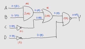
[Digital logic circuit]
It's a question
Calculate 1) Path Delay, 2) Critical Path Delay, and 3) Circuit Delay in the following circuits
( NEED NEAT HANDWRITTEN SOLUTION ONLY OTHERWISE DOWNVOTE)

Transcribed Image Text:A
B
0.505
D
6.5n5
(0.15h5
xts
Susio
ins
Dok
ins
And
2.ons
0.505
0.ins
0.515
OR
12.01s
0.5n5
susir
Susio
Expert Solution
This question has been solved!
Explore an expertly crafted, step-by-step solution for a thorough understanding of key concepts.
Step by stepSolved in 3 steps with 3 images

Knowledge Booster
Learn more about
Need a deep-dive on the concept behind this application? Look no further. Learn more about this topic, electrical-engineering and related others by exploring similar questions and additional content below.Similar questions
- 1. Design an Excess-3 (Ex-3) checker circuit for an input of 4-bits. (the output is logic 1 if the input is a valid Excess-3 and is 0 otherwise).arrow_forward5/ Select a suitable example for combinational logic circuit. A) None of the given choices B) Decoders C) Latches D ) PLAarrow_forwardWhich of the following are part of the Arduino microcomputer. The answer could be more than onearrow_forward
- Design a combinational circuit using multiplexer for a car chime based on thefollowing system: A car chime or bell will sound if the output of the logic circuit(X) is set to a logic ‘1’. The chime is to be sounded for either of the followingconditions:• if the headlights are left on when the engine is turned off and• if the engine is off and the key is in the ignition when the door is opened.Use the following input names and nomenclature in the design process:• ‘E’ – Engine. ‘1’ if the engine is ON and ‘0’ if the engine is OFF• ‘L’ – Lights. ‘1’ if the lights are ON and ‘0’ if the lights are OFF• ‘K’ – Key. ‘1’ if the key is in the ignition and ‘0’ if the key is not in the ignition• ‘D’ – Door. ‘1’ the door is open and ‘0’ if the door is closed• ‘X’ – Output to Chime. ‘1’ is chime is ON and ‘0’ if chime is OFFarrow_forwarda) Buses are the conductive channels found in the circuitry of a microprocessor. This means that there is potential for current to flow among the various parts. Expertly classify these buses according to their function and describe how they interact with microprocessors.b) In a microprocessor, what is the distinction between data and instructions?arrow_forwardQuestion 1) If six NOT (inverters) gates are connected in series and the input to the first gate is a LOW (0) the output of the FIFTH. gate will be:arrow_forward
- Implement the logic circuit in Figure 2 using only NAND gate A B C Xarrow_forwardbuses are conductive pathways in a microprocessor's circuitry. Therefore, current may flow among the various parts. Expertly classify and explain the functions of these buses as they pertain to microprocessors. In a microprocessor, what role do data and instructions play? b)arrow_forwardIn motor control of train, IGBT control AC motor save more energy than GTO due to less switching loss. State THREE more reasons why IGBT use in motor control has many advantages over GTO. If one of the freewheeling diode in your single phase inverter in above settings has reverse recovery failure. Describe what would happen to the circuit.arrow_forward
- 30) Coils labeled ( S ) and ( R )A) must appear in that order (S before R) in a ladder logic programB) may be used only in subroutines in programs for Siemens PLCsC) are Short and Repeated coils, used in timing programsD) may be used instead of a seal-in arrangement to provide latchingarrow_forwardLOGIC GATE ( NEED ONLY HANDWRITTEN SOLUTION PLEASE OTHERWISE DOWNVOTE).arrow_forward5) Draw the circuit diagram using diode and write the truth table of a logic gates whose output will be the logical OR operation of two inputs.arrow_forward
arrow_back_ios
SEE MORE QUESTIONS
arrow_forward_ios
Recommended textbooks for you
 Introductory Circuit Analysis (13th Edition)Electrical EngineeringISBN:9780133923605Author:Robert L. BoylestadPublisher:PEARSON
 Delmar's Standard Textbook Of ElectricityElectrical EngineeringISBN:9781337900348Author:Stephen L. HermanPublisher:Cengage Learning
 Programmable Logic ControllersElectrical EngineeringISBN:9780073373843Author:Frank D. PetruzellaPublisher:McGraw-Hill Education
 Fundamentals of Electric CircuitsElectrical EngineeringISBN:9780078028229Author:Charles K Alexander, Matthew SadikuPublisher:McGraw-Hill Education
 Electric Circuits. (11th Edition)Electrical EngineeringISBN:9780134746968Author:James W. Nilsson, Susan RiedelPublisher:PEARSON
 Engineering ElectromagneticsElectrical EngineeringISBN:9780078028151Author:Hayt, William H. (william Hart), Jr, BUCK, John A.Publisher:Mcgraw-hill Education,

Introductory Circuit Analysis (13th Edition)
Electrical Engineering
ISBN:9780133923605
Author:Robert L. Boylestad
Publisher:PEARSON

Delmar's Standard Textbook Of Electricity
Electrical Engineering
ISBN:9781337900348
Author:Stephen L. Herman
Publisher:Cengage Learning

Programmable Logic Controllers
Electrical Engineering
ISBN:9780073373843
Author:Frank D. Petruzella
Publisher:McGraw-Hill Education

Fundamentals of Electric Circuits
Electrical Engineering
ISBN:9780078028229
Author:Charles K Alexander, Matthew Sadiku
Publisher:McGraw-Hill Education

Electric Circuits. (11th Edition)
Electrical Engineering
ISBN:9780134746968
Author:James W. Nilsson, Susan Riedel
Publisher:PEARSON

Engineering Electromagnetics
Electrical Engineering
ISBN:9780078028151
Author:Hayt, William H. (william Hart), Jr, BUCK, John A.
Publisher:Mcgraw-hill Education,