
Introductory Circuit Analysis (13th Edition)
13th Edition
ISBN: 9780133923605
Author: Robert L. Boylestad
Publisher: PEARSON
expand_more
expand_more
format_list_bulleted
Related questions
Concept explainers
Question
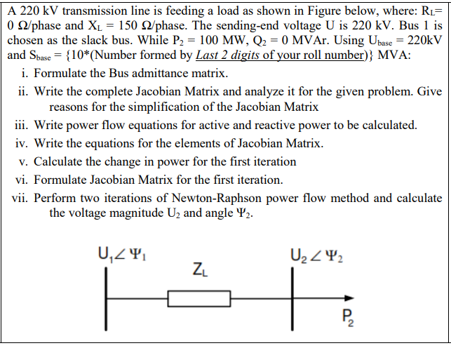

Transcribed Image Text:A 220 kV transmission line is feeding a load as shown in Figure below, where: R1=
O O/phase and XL = 150 Q/phase. The sending-end voltage U is 220 kV. Bus 1 is
chosen as the slack bus. While P2 = 100 MW, Q2 = 0 MVAr. Using Ubase = 220kV
and Sbase = {10*(Number formed by Last 2 digits of your roll number)} MVA:
i. Formulate the Bus admittance matrix.
ii. Write the complete Jacobian Matrix and analyze it for the given problem. Give
reasons for the simplification of the Jacobian Matrix
iii. Write power flow equations for active and reactive power to be calculated.
iv. Write the equations for the elements of Jacobian Matrix.
v. Calculate the change in power for the first iteration
vi. Formulate Jacobian Matrix for the first iteration.
vii. Perform two iterations of Newton-Raphson power flow method and calculate
the voltage magnitude U2 and angle Y2.
U2 Z42
Expert Solution
This question has been solved!
Explore an expertly crafted, step-by-step solution for a thorough understanding of key concepts.

This is a popular solution

Trending nowThis is a popular solution!

Step by stepSolved in 2 steps

Knowledge Booster


Learn more about
Need a deep-dive on the concept behind this application? Look no further. Learn more about this topic, electrical-engineering and related others by exploring similar questions and additional content below.Similar questions
- The bus impedance matrix for a three-bus power system has per-unit elements as: Z11 = 0.5 Z12 = 0.4 Z13 = 0.8 Z21 = 1 Z22 = 0.5 Z23 = 0.6 Z31 = 0.5 Z32 = 1.2 Z33 = 1 Prefault voltage is 1 per unit and prefault current is neglected. A three-phase short circuit occurs at bus 3. Determine the subtransient fault current. Round your answer to 2 decimal places.arrow_forwardQ2: The constants of a 275 KV transmission line are A = 0.8525° and B = 200275° 0/phase. Draw the circle diagram to determine the power and power angle at unity power factor that can be received if the voltage profile at each end is to be maintained at 275 KV. What type a rating of compensating equipment will be required if the load is 150 MW at unity power factor with same voltage profile. (5.5 mark)arrow_forward
Recommended textbooks for you
- Introductory Circuit Analysis (13th Edition)Electrical EngineeringISBN:9780133923605Author:Robert L. BoylestadPublisher:PEARSON
 Delmar's Standard Textbook Of ElectricityElectrical EngineeringISBN:9781337900348Author:Stephen L. HermanPublisher:Cengage Learning
 Programmable Logic ControllersElectrical EngineeringISBN:9780073373843Author:Frank D. PetruzellaPublisher:McGraw-Hill Education
  Fundamentals of Electric CircuitsElectrical EngineeringISBN:9780078028229Author:Charles K Alexander, Matthew SadikuPublisher:McGraw-Hill Education
 Electric Circuits. (11th Edition)Electrical EngineeringISBN:9780134746968Author:James W. Nilsson, Susan RiedelPublisher:PEARSON
 Engineering ElectromagneticsElectrical EngineeringISBN:9780078028151Author:Hayt, William H. (william Hart), Jr, BUCK, John A.Publisher:Mcgraw-hill Education,
Introductory Circuit Analysis (13th Edition)
Electrical Engineering
ISBN:9780133923605
Author:Robert L. Boylestad
Publisher:PEARSON
Delmar's Standard Textbook Of Electricity
Electrical Engineering
ISBN:9781337900348
Author:Stephen L. Herman
Publisher:Cengage Learning
Programmable Logic Controllers
Electrical Engineering
ISBN:9780073373843
Author:Frank D. Petruzella
Publisher:McGraw-Hill Education
Fundamentals of Electric Circuits
Electrical Engineering
ISBN:9780078028229
Author:Charles K Alexander, Matthew Sadiku
Publisher:McGraw-Hill Education
Electric Circuits. (11th Edition)
Electrical Engineering
ISBN:9780134746968
Author:James W. Nilsson, Susan Riedel
Publisher:PEARSON
Engineering Electromagnetics
Electrical Engineering
ISBN:9780078028151
Author:Hayt, William H. (william Hart), Jr, BUCK, John A.
Publisher:Mcgraw-hill Education,