Introductory Circuit Analysis (13th Edition)
13th Edition
ISBN: 9780133923605
Author: Robert L. Boylestad
Publisher: PEARSON
expand_more
expand_more
format_list_bulleted
Question

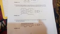
Transcribed Image Text:B
FIGURE 3-78
8. The input waveforms applied to a 4-input AND gate are as indicated in Figure 3-81. The
output of the AND gate is fed to an inverter. Draw the net output waveform of this system.
X
FIGURE 3-81
17. For the set of input waveforms in Figure 3-83, determine the output for the gate shown and
draw the timing diagram.
X
B
FIGURE 3-83
24
Expert Solution
This question has been solved!
Explore an expertly crafted, step-by-step solution for a thorough understanding of key concepts.
This is a popular solution
Trending nowThis is a popular solution!
Step by stepSolved in 2 steps with 2 images

Knowledge Booster
Learn more about
Need a deep-dive on the concept behind this application? Look no further. Learn more about this topic, electrical-engineering and related others by exploring similar questions and additional content below.Similar questions
- 2. A. What parameters can be measured with a digital multimeter (DMM)? B. How does the DMM measure each parameter given that its internal circuitry actually only responds to voltage? C. What is the input resistance of the DMM on voltage ranges and why is this important? D. What voltage will the DMM read in the circuit below? Show computations. www DMMarrow_forwardQ4) Design an arithmetic logic unit (ALU) that can do the following operations (A AND B, A-B, B-A, A OR B. A+B, NOT A and NOT B) and write the Truth Table for each unit?arrow_forwardcan i have a step by step pleasearrow_forward
- What are the dc output voltages V1 and V2 for the rectifier circuit shown. if vI = 40sin377t and C =20,000 μF?arrow_forwardIn step 2 you measured the voltage across each of the LEDs. This is their “forward voltage” that is referred to in the LED component page, which is the voltage required to light the LEDs. Notice that the combined forward voltage of D1 and D2 is greater than 3.3V, the LEDs will not light up at all. You should also have noticed that the forward voltage for one of the LEDS is lower than the forward voltage for the other LED. Some LEDS require less energy to light than others. Since D1 and D2 are in series, the same current will flow through each, but the different voltages across each LED reflect the different energy requirements. Finish each statement below, bears on this information and in the measurements you took in step 2 The measured forward voltage across D1 in this step is ________ The measured forward voltage across D2 in this step is ________arrow_forwardQ3. For the 4-input NAND gate in Figure 3-33, operating as a negative-OR gate, determine the output with respect to the inputs. A B Carrow_forward
- The diodes in the following circuit are made of Silicon, that is, VD = 0.7 V. Determine IDI. ID. IDs and VA when (a) R3 = 14 kQ, R4 = 24 kQ; (b) R3 = 3.3 k2, R4 = 5.2 k D3 1p3 wwog +15 V -10 V D₂ Ip2 R4 R = 6.15 kΩ D₁ Ip R3 -5 V wli - Vo R₂ = 2kQ2arrow_forwardWhich statement is not true about an extrinsic semiconductor? They do not have equal numbers charge carriers. Their impurities do not affect their electrical behavior. They can be doped with another element by a process known as doping process. They are chemically not pure. Their electrical properties can be tuned.arrow_forward30. For the input waveforms in Figure 5-61, what logic circuit will generate the output waveform shown? A Inputs B C Output X FIGURE 5-61 ad points in the proper rela.arrow_forward
- Rather than use transistors your friend W. Too wants to use diodes to implement logic gates. He shows you the circuit he designed shown in figure 5. If A and B can swing all the way from 0 V to VDD, does the circuit implement a logic gate? If so what gate is it and what is its static discipline? Assume the diode is modeled by an ideal diode with a series resistance RD V. DD R₁ L ΟΥ AO Bo Figure 5: Diode Based Logic Gatearrow_forwardExplain diagramarrow_forwardNeeds Complete solution with 100 % accuracy.arrow_forward
arrow_back_ios
SEE MORE QUESTIONS
arrow_forward_ios
Recommended textbooks for you
 Introductory Circuit Analysis (13th Edition)Electrical EngineeringISBN:9780133923605Author:Robert L. BoylestadPublisher:PEARSON
 Delmar's Standard Textbook Of ElectricityElectrical EngineeringISBN:9781337900348Author:Stephen L. HermanPublisher:Cengage Learning
 Programmable Logic ControllersElectrical EngineeringISBN:9780073373843Author:Frank D. PetruzellaPublisher:McGraw-Hill Education
 Fundamentals of Electric CircuitsElectrical EngineeringISBN:9780078028229Author:Charles K Alexander, Matthew SadikuPublisher:McGraw-Hill Education
 Electric Circuits. (11th Edition)Electrical EngineeringISBN:9780134746968Author:James W. Nilsson, Susan RiedelPublisher:PEARSON
 Engineering ElectromagneticsElectrical EngineeringISBN:9780078028151Author:Hayt, William H. (william Hart), Jr, BUCK, John A.Publisher:Mcgraw-hill Education,

Introductory Circuit Analysis (13th Edition)
Electrical Engineering
ISBN:9780133923605
Author:Robert L. Boylestad
Publisher:PEARSON

Delmar's Standard Textbook Of Electricity
Electrical Engineering
ISBN:9781337900348
Author:Stephen L. Herman
Publisher:Cengage Learning

Programmable Logic Controllers
Electrical Engineering
ISBN:9780073373843
Author:Frank D. Petruzella
Publisher:McGraw-Hill Education

Fundamentals of Electric Circuits
Electrical Engineering
ISBN:9780078028229
Author:Charles K Alexander, Matthew Sadiku
Publisher:McGraw-Hill Education

Electric Circuits. (11th Edition)
Electrical Engineering
ISBN:9780134746968
Author:James W. Nilsson, Susan Riedel
Publisher:PEARSON

Engineering Electromagnetics
Electrical Engineering
ISBN:9780078028151
Author:Hayt, William H. (william Hart), Jr, BUCK, John A.
Publisher:Mcgraw-hill Education,