
Elements Of Electromagnetics
7th Edition
ISBN: 9780190698614
Author: Sadiku, Matthew N. O.
Publisher: Oxford University Press
expand_more
expand_more
format_list_bulleted
Related questions
Concept explainers
Question
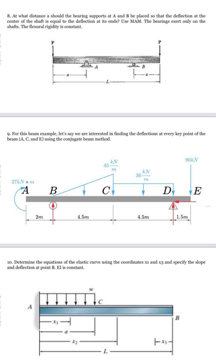
8. At what distance a should the bearing supports at A and B be placed so that the deflection at the enter of the shaft is equal to the deflection at its ends? Use MAM. The bearings exert only on the hafts. The flexural rigidity is constant.
9. For this beam example, let's say we are interested in finding the deflections at every key point of the beam (A, C, and E) using the conjugate beam method.
10. Determine the equations of the elastic curve using the coordinates x1 and x3 and specify the slope and deflection at point B. El is constant.

Transcribed Image Text:8. At what distance a should the bearing supports at A and B be placed so that the deflection at the
center of the shaft is equal to the deflection at its ends? Use MAM. The bearings exert only on the
shafts. The flexural rigidity is constant.
9. For this beam example, let's say we are interested in finding the deflections at every key point of the
beam (A, C, and E) using the conjugate beam method.
90KN
kN
45
m
kN
36
27KN• m
B
C
D
E
2m
4.5m
4.5m
1.5m
10. Determine the equations of the elastic curve using the coordinates x1 and x3 and specify the slope
and deflection at point B. EI is constant.
C
Expert Solution
This question has been solved!
Explore an expertly crafted, step-by-step solution for a thorough understanding of key concepts.

Step by stepSolved in 2 steps with 2 images

Knowledge Booster


Learn more about
Need a deep-dive on the concept behind this application? Look no further. Learn more about this topic, mechanical-engineering and related others by exploring similar questions and additional content below.Similar questions
- Consider the beam with properties and loadings as described in the figure and parameter table. Use superposition to find the angles of deflection at A and C (in degrees). M neo 0A = A 0c= 7////////// CC 2022 Cathy Zupke parameter L W BY NC SA Alloy Beam Type value 6 50 65 A992 Steel W310 x 67 O B O units W m kN/m kN m . Carrow_forwardAt what distance, "a" should the bearing supports at A and B be placed so that the displacement at the center of the shaft is equal to the deflection at its ends? The bearings exert only vertical reactions on the shaft. Use conjugate beam method. (EI is constant)arrow_forwardBP1: A cantilevered beam of constant El and length L is supporting a concentrated load F at x=L. Determine the deflection of the beam at L using Catigliano's method.arrow_forward
- Find the slope and deflection equations for the beam shown. Determine thevertical deflection of point C. Consider P = 120 kN, l = 5m, a = 80 cm. EI = constant. Method of Double Integrationarrow_forwardAnswer the value of the deflection at point C. Enter your answer in mm to three decimal places. Assume the positive direction of deflection in the positive direction of v axis.arrow_forwardDetermine the deflection at Point C of the beam shown below (negative is down). P = 16 kN wo = 29 kN/m E = 192 GPa I = 94.145x10⁻⁶ m4 Express your answer using three significant figures and ensure that it is in mm.arrow_forward
- Question 1 Precision Engineering Contractors was awarded a government contract to construct a bridge joining two neighboring communities. The bridge ABC is simply supported at A and B 2 m apart and carries a uniformly distributed load of 50 KN/m between A and B, together with a concentrated load of 25 KN on an overhang at C, 0.5 m from B. Make a neat sketch of this bridge and calculate the maximum deflection from point A using Macaulay's Method. Take EI = 21 MNm²arrow_forwardHi please present the solution clearly (preferabely on paper) with all steps so it is easier to understand since I have asked this question multiple times and I still don't get it. Thank you!arrow_forwardAn aluminum tube with outside diameter of 2 in and inside diameter of 1.5 in is cantilevered and loaded as shown. Using the formulas in Table A-9 and superposition, find the deflection at B. Take the magnitude of force (F1) to be 307 lbf and the magnitude of force (F2) to be 204 lbf. y 2 ft F1 A 2 ft F2 The deflection at Bis 20.59 X inch in the downward direction.arrow_forward
arrow_back_ios
arrow_forward_ios
Recommended textbooks for you
- Elements Of ElectromagneticsMechanical EngineeringISBN:9780190698614Author:Sadiku, Matthew N. O.Publisher:Oxford University Press
 Mechanics of Materials (10th Edition)Mechanical EngineeringISBN:9780134319650Author:Russell C. HibbelerPublisher:PEARSON
 Thermodynamics: An Engineering ApproachMechanical EngineeringISBN:9781259822674Author:Yunus A. Cengel Dr., Michael A. BolesPublisher:McGraw-Hill Education
  Control Systems EngineeringMechanical EngineeringISBN:9781118170519Author:Norman S. NisePublisher:WILEY
 Mechanics of Materials (MindTap Course List)Mechanical EngineeringISBN:9781337093347Author:Barry J. Goodno, James M. GerePublisher:Cengage Learning
 Engineering Mechanics: StaticsMechanical EngineeringISBN:9781118807330Author:James L. Meriam, L. G. Kraige, J. N. BoltonPublisher:WILEY
Elements Of Electromagnetics
Mechanical Engineering
ISBN:9780190698614
Author:Sadiku, Matthew N. O.
Publisher:Oxford University Press
Mechanics of Materials (10th Edition)
Mechanical Engineering
ISBN:9780134319650
Author:Russell C. Hibbeler
Publisher:PEARSON
Thermodynamics: An Engineering Approach
Mechanical Engineering
ISBN:9781259822674
Author:Yunus A. Cengel Dr., Michael A. Boles
Publisher:McGraw-Hill Education
Control Systems Engineering
Mechanical Engineering
ISBN:9781118170519
Author:Norman S. Nise
Publisher:WILEY
Mechanics of Materials (MindTap Course List)
Mechanical Engineering
ISBN:9781337093347
Author:Barry J. Goodno, James M. Gere
Publisher:Cengage Learning
Engineering Mechanics: Statics
Mechanical Engineering
ISBN:9781118807330
Author:James L. Meriam, L. G. Kraige, J. N. Bolton
Publisher:WILEY