Introductory Circuit Analysis (13th Edition)
13th Edition
ISBN: 9780133923605
Author: Robert L. Boylestad
Publisher: PEARSON
expand_more
expand_more
format_list_bulleted
Question
thumb_up100%

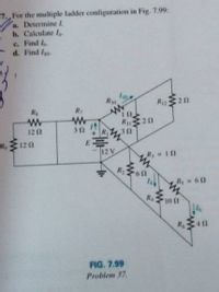
Transcribed Image Text:7. For the multiple tadder configuration in Fig. 7.99:
a. Determine 1.
b. Calculate I
c. Find I
d. Find Io
Ro
C20
R
R 212
R
E
12 V
121
32
R, 120
R 10
R 60
Rs
R
4 11
FIG. 7.99
Problem 37.
Expert Solution
This question has been solved!
Explore an expertly crafted, step-by-step solution for a thorough understanding of key concepts.
This is a popular solution
Trending nowThis is a popular solution!
Step by stepSolved in 3 steps with 3 images

Knowledge Booster
Learn more about
Need a deep-dive on the concept behind this application? Look no further. Learn more about this topic, electrical-engineering and related others by exploring similar questions and additional content below.Similar questions
- Using the Norton equivalent for the circuit shown in the following figure, determine its normal range of load current values (Fig. 7.55b). RL=50 ohms ans. = 63.17mA RL=150 ohms ans. 32.43mA (May require Thevenin Theorem or Norton Theorem) Help me to get the exact answers given..arrow_forwardIt explains what formula is used to solve the problem step by step and why that formula is used. Please explain in an easy to understand wayAlso, I would like you to explain how to solve the problemarrow_forwardPlease answer question 7 with details on how to do it. Make handwriting legible please. Thank you.arrow_forward
- can you doing this with detail explaination..thank you!arrow_forwardDC EXAMPLE 7.1 Determine the following for the network of Fig. 7.6: VGSQ a. VDD b. IDg c. VDS. d. Vp. ´e. VG. f. Vs. + 1 ΜΩ 2 V G + VGS Ter 16. V 2kQ D -S 1pss = 10 mA DSS V₂ = -8 V FIG. 7.6 Figure ? ? Example of a Fixed-Bias Circuit. 11 VOD - ID Rp 16 - 1arrow_forwardI have the last attempt, please, I want the complete solution, sir.arrow_forward
- Textbook Question BA Chapter 7, Problem 3P Determine RT for the networks in Fig. 7.66. RT www 492 402 (a) www 4 Ω 10 Ω Fig. 7.66 Problem 3. Fig. 7.66 402 RT www 10 Ω (b) 10 Ω www 10 Ω RT U.O 10 ΩΣ (c) www 1.2 Ω 8.20arrow_forward1. Find the equivalent capacitance for the circuit below if the capacitance for each is C. 2. A network of resistors, each of resistance R, is shown in Fig. 7.1. A B. •Y R Fig. 7.1 Calculate the total resistance interms of R between A and C B and X i. i. ii. A and Zarrow_forward
arrow_back_ios
arrow_forward_ios
Recommended textbooks for you
 Introductory Circuit Analysis (13th Edition)Electrical EngineeringISBN:9780133923605Author:Robert L. BoylestadPublisher:PEARSON
 Delmar's Standard Textbook Of ElectricityElectrical EngineeringISBN:9781337900348Author:Stephen L. HermanPublisher:Cengage Learning
 Programmable Logic ControllersElectrical EngineeringISBN:9780073373843Author:Frank D. PetruzellaPublisher:McGraw-Hill Education
 Fundamentals of Electric CircuitsElectrical EngineeringISBN:9780078028229Author:Charles K Alexander, Matthew SadikuPublisher:McGraw-Hill Education
 Electric Circuits. (11th Edition)Electrical EngineeringISBN:9780134746968Author:James W. Nilsson, Susan RiedelPublisher:PEARSON
 Engineering ElectromagneticsElectrical EngineeringISBN:9780078028151Author:Hayt, William H. (william Hart), Jr, BUCK, John A.Publisher:Mcgraw-hill Education,

Introductory Circuit Analysis (13th Edition)
Electrical Engineering
ISBN:9780133923605
Author:Robert L. Boylestad
Publisher:PEARSON

Delmar's Standard Textbook Of Electricity
Electrical Engineering
ISBN:9781337900348
Author:Stephen L. Herman
Publisher:Cengage Learning

Programmable Logic Controllers
Electrical Engineering
ISBN:9780073373843
Author:Frank D. Petruzella
Publisher:McGraw-Hill Education

Fundamentals of Electric Circuits
Electrical Engineering
ISBN:9780078028229
Author:Charles K Alexander, Matthew Sadiku
Publisher:McGraw-Hill Education

Electric Circuits. (11th Edition)
Electrical Engineering
ISBN:9780134746968
Author:James W. Nilsson, Susan Riedel
Publisher:PEARSON

Engineering Electromagnetics
Electrical Engineering
ISBN:9780078028151
Author:Hayt, William H. (william Hart), Jr, BUCK, John A.
Publisher:Mcgraw-hill Education,