Question
Plz solve correctly

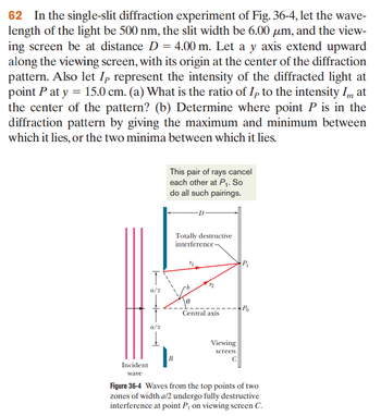
Transcribed Image Text:62 In the single-slit diffraction experiment of Fig. 36-4, let the wave-
length of the light be 500 nm, the slit width be 6.00 um, and the view-
ing screen be at distance D = 4.00 m. Let a y axis extend upward
along the viewing screen, with its origin at the center of the diffraction
pattern. Also let Ip represent the intensity of the diffracted light at
point P at y = 15.0 cm. (a) What is the ratio of Ip to the intensity Im at
the center of the pattern? (b) Determine where point P is in the
diffraction pattern by giving the maximum and minimum between
which it lies, or the two minima between which it lies.
Incident
wave
T
a/2
a/2
Į
This pair of rays cancel
each other at P₁. So
do all such pairings.
B
Totally destructive
interference
11
0
Central axis
Viewing
screen
P₁
Po
Figure 36-4 Waves from the top points of two
zones of width a/2 undergo fully destructive
interference at point P₁ on viewing screen C.
Expert Solution
This question has been solved!
Explore an expertly crafted, step-by-step solution for a thorough understanding of key concepts.
Step by stepSolved in 6 steps with 15 images

Knowledge Booster
Similar questions