
Introductory Circuit Analysis (13th Edition)
13th Edition
ISBN: 9780133923605
Author: Robert L. Boylestad
Publisher: PEARSON
expand_more
expand_more
format_list_bulleted
Related questions
Question
Can you help me understand what are they talking about

Transcribed Image Text:6.3 THE RLC CIRCUIT
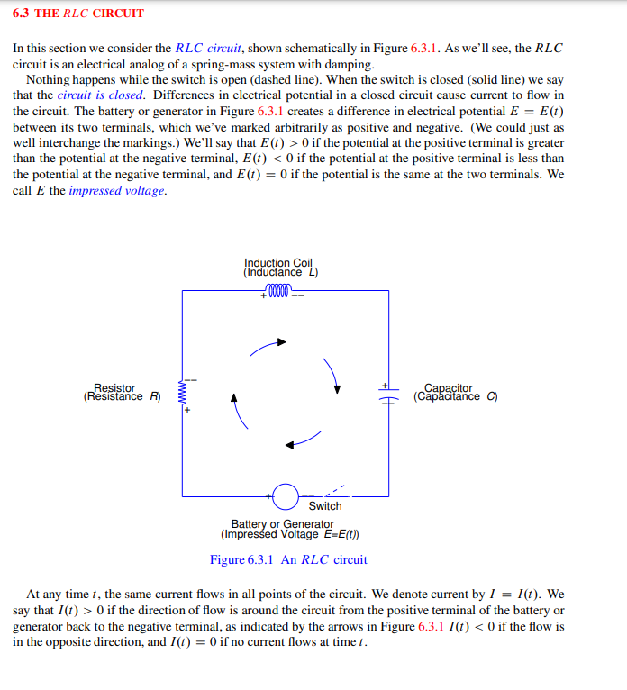
In this section we consider the RLC circuit, shown schematically in Figure 6.3.1. As we'll see, the RLC
circuit is an electrical analog of a spring-mass system with damping.
Nothing happens while the switch is open (dashed line). When the switch is closed (solid line) we say
that the circuit is closed. Differences in electrical potential in a closed circuit cause current to flow in
the circuit. The battery or generator in Figure 6.3.1 creates a difference in electrical potential E = E(t)
between its two terminals, which we've marked arbitrarily as positive and negative. (We could just as
well interchange the markings.) We'll say that E (t) > 0 if the potential at the positive terminal is greater
than the potential at the negative terminal, E(t) < 0 if the potential at the positive terminal is less than
the potential at the negative terminal, and E(1) = 0 if the potential is the same at the two terminals. We
call E the impressed voltage.
Resistor
(Resistance R)
www+
Induction Coil
(Inductance L)
+00000
Switch
Battery or Generator
(Impressed Voltage E=E(t))
Figure 6.3.1 An RLC circuit
Capacitor
(Capacitance C)
At any time 1, the same current flows in all points of the circuit. We denote current by I = 1(t). We
say that I(1) > 0 if the direction of flow is around the circuit from the positive terminal of the battery or
generator back to the negative terminal, as indicated by the arrows in Figure 6.3.1 I(t) < 0 if the flow is
in the opposite direction, and I(t) = 0 if no current flows at time 1.

Transcribed Image Text:Differences in potential occur at the resistor, induction coil, and capacitor in Figure 6.3.1. Note that the
two sides of each of these components are also identified as positive and negative. The voltage drop across
each component is defined to be the potential on the positive side of the component minus the potential
on the negative side. This terminology is somewhat misleading, since "drop" suggests a decrease even
though changes in potential are signed quantities and therefore may be increases. Nevertheless, we'll go
along with tradition and call them voltage drops. The voltage drop across the resistor in Figure 6.3.1 is
given by
VR = IR,
(6.3.1)
where I is current and R is a positive constant, the resistance of the resistor. The voltage drop across the
induction coil is given by
and
V₁ = L
where L is a positive constant, the inductance of the coil.
A capacitor stores electrical charge Q = Q(t), which is related to the current in the circuit by the
equation
Q(1) = Qo+ f 1(1) dr.
where Qo is the charge on the capacitor at t = 0. The voltage drop across a capacitor is given by
Vc = 2/₁
Table 6.3.8. Electrical Units
1 volt =
=
=
1 ampere =
dI
Symbol
E
I
LI',
Q
R
L
с
Section 6.3 The RLC Circuit 291
where C is a positive constant, the capacitance of the capacitor.
Table 6.3.8 names the units for the quantities that we've discussed. The units are defined so that
1 ampere - 1 ohm
1 henry - 1 ampere/second
1 coulomb/ farad
1 coulomb/second.
Name
Impressed Voltage
Current
Charge
Resistance
Inductance
Capacitance
(6.3.2)
Unit
volt
ampere
coulomb
ohm
henry
farad
(6.3.3)
(6.3.4)
Expert Solution
This question has been solved!
Explore an expertly crafted, step-by-step solution for a thorough understanding of key concepts.

This is a popular solution

Trending nowThis is a popular solution!

Step by stepSolved in 3 steps

Knowledge Booster


Learn more about
Need a deep-dive on the concept behind this application? Look no further. Learn more about this topic, electrical-engineering and related others by exploring similar questions and additional content below.Similar questions
Recommended textbooks for you
- Introductory Circuit Analysis (13th Edition)Electrical EngineeringISBN:9780133923605Author:Robert L. BoylestadPublisher:PEARSON
 Delmar's Standard Textbook Of ElectricityElectrical EngineeringISBN:9781337900348Author:Stephen L. HermanPublisher:Cengage Learning
 Programmable Logic ControllersElectrical EngineeringISBN:9780073373843Author:Frank D. PetruzellaPublisher:McGraw-Hill Education
  Fundamentals of Electric CircuitsElectrical EngineeringISBN:9780078028229Author:Charles K Alexander, Matthew SadikuPublisher:McGraw-Hill Education
 Electric Circuits. (11th Edition)Electrical EngineeringISBN:9780134746968Author:James W. Nilsson, Susan RiedelPublisher:PEARSON
 Engineering ElectromagneticsElectrical EngineeringISBN:9780078028151Author:Hayt, William H. (william Hart), Jr, BUCK, John A.Publisher:Mcgraw-hill Education,
Introductory Circuit Analysis (13th Edition)
Electrical Engineering
ISBN:9780133923605
Author:Robert L. Boylestad
Publisher:PEARSON
Delmar's Standard Textbook Of Electricity
Electrical Engineering
ISBN:9781337900348
Author:Stephen L. Herman
Publisher:Cengage Learning
Programmable Logic Controllers
Electrical Engineering
ISBN:9780073373843
Author:Frank D. Petruzella
Publisher:McGraw-Hill Education
Fundamentals of Electric Circuits
Electrical Engineering
ISBN:9780078028229
Author:Charles K Alexander, Matthew Sadiku
Publisher:McGraw-Hill Education
Electric Circuits. (11th Edition)
Electrical Engineering
ISBN:9780134746968
Author:James W. Nilsson, Susan Riedel
Publisher:PEARSON
Engineering Electromagnetics
Electrical Engineering
ISBN:9780078028151
Author:Hayt, William H. (william Hart), Jr, BUCK, John A.
Publisher:Mcgraw-hill Education,