Structural Analysis
6th Edition
ISBN: 9781337630931
Author: KASSIMALI, Aslam.
Publisher: Cengage,
expand_more
expand_more
format_list_bulleted
Question

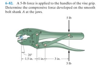
Transcribed Image Text:6-82. A 5-lb force is applied to the handles of the vise grip.
Determine the compressive force developed on the smooth
bolt shank A at the jaws.
0.75 in.
AAAAAAAA
20°
-1.5 in.1 in.
3 in.
5 lb
5 lb
Expert Solution
This question has been solved!
Explore an expertly crafted, step-by-step solution for a thorough understanding of key concepts.
Step by stepSolved in 4 steps with 3 images

Knowledge Booster
Learn more about
Need a deep-dive on the concept behind this application? Look no further. Learn more about this topic, civil-engineering and related others by exploring similar questions and additional content below.Similar questions
- Required information The rigid bar AD is supported by two steel wires of 16 -in. diameter (E= 29 x 106 psi) and a pin and bracket at A. The wires were initially taut when a 240-lb load P was applied at D. F 8 in. E 10 in. В 12 in. 12 in. 12 in. Determine the additional tension in each wire when the load P is applied. The additional tension in wire BE is Ib. The additional tension in wire CFis Ib.arrow_forwardThe force in member EF using the method of section. [Handwritten solution required]arrow_forward"1-80. Determine the maximum allowable torque T that can be transmitted by the joint. The shear pin A has a diameter of 25 mm, and it is made from a material having a failure shear stress of Tai 150 MPa. Apply a factor of safety of 3 against failure. 100 mmarrow_forward
- 1-7. Determine the resultant internal loading on the cross section through point D of the pliers. There is a pin at A, and the jaws at B are smooth. 20 N 20 N -120 mm- 80 mm 30° 40 mm 15 mm Barrow_forwardDetermine the reactions at the supports. Draw FBD first. a). CLEARLY SHOW ALL WORK. B F G TH 200 Ib Scale: I unit -5 ft 200 1Ь 200 Ib Reaction at A (x-direction) Reaction at A (y-direction) = _[lb] _[lb] Reaction at E (x-direction) = Reaction at E (y-direction) =, [Ib] fib] b) Determine the ZERO FORCE MEMBERS. Fully justify your answer. Zero force member #1 (if any) = Zero force member #2 (if any) = Zero force member #3 (if any) =. c) Determine the loads in members: AF, AB and BC. Fully justify your answer. Load in member AB =. Load in member AF = Load in member BC =. Ib Ib Ibarrow_forward2. Calculate the internal forces in the bar GF and GD in a roof truss as shownbelow. For each bar, indicate if the internal force is tensile or compressive. Usethe section method (snittmetoden). Point A has simple support and D has rollersupport.arrow_forward
arrow_back_ios
arrow_forward_ios
Recommended textbooks for you

 Structural Analysis (10th Edition)Civil EngineeringISBN:9780134610672Author:Russell C. HibbelerPublisher:PEARSON
 Principles of Foundation Engineering (MindTap Cou...Civil EngineeringISBN:9781337705028Author:Braja M. Das, Nagaratnam SivakuganPublisher:Cengage Learning
 Fundamentals of Structural AnalysisCivil EngineeringISBN:9780073398006Author:Kenneth M. Leet Emeritus, Chia-Ming Uang, Joel LanningPublisher:McGraw-Hill Education
 Traffic and Highway EngineeringCivil EngineeringISBN:9781305156241Author:Garber, Nicholas J.Publisher:Cengage Learning


Structural Analysis (10th Edition)
Civil Engineering
ISBN:9780134610672
Author:Russell C. Hibbeler
Publisher:PEARSON

Principles of Foundation Engineering (MindTap Cou...
Civil Engineering
ISBN:9781337705028
Author:Braja M. Das, Nagaratnam Sivakugan
Publisher:Cengage Learning

Fundamentals of Structural Analysis
Civil Engineering
ISBN:9780073398006
Author:Kenneth M. Leet Emeritus, Chia-Ming Uang, Joel Lanning
Publisher:McGraw-Hill Education


Traffic and Highway Engineering
Civil Engineering
ISBN:9781305156241
Author:Garber, Nicholas J.
Publisher:Cengage Learning