Structural Analysis
6th Edition
ISBN: 9781337630931
Author: KASSIMALI, Aslam.
Publisher: Cengage,
expand_more
expand_more
format_list_bulleted
Concept explainers
Question

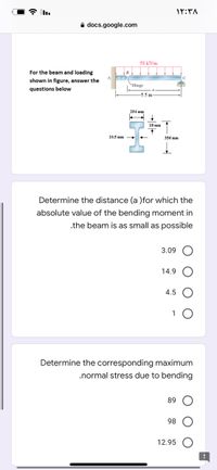
Transcribed Image Text:A docs.google.com
58 kN/m
For the beam and loading
shown in figure, answer the
Hinge
questions below
-5.5 m
254 mm
18 mm
10.5 mm
356 mm
Determine the distance (a )for which the
absolute value of the bending moment in
.the beam is as small as possible
3.09
14.9
4.5
1
Determine the corresponding maximum
.normal stress due to bending
89
98
12.95
Expert Solution
This question has been solved!
Explore an expertly crafted, step-by-step solution for a thorough understanding of key concepts.
This is a popular solution
Trending nowThis is a popular solution!
Step by stepSolved in 3 steps with 2 images

Knowledge Booster
Learn more about
Need a deep-dive on the concept behind this application? Look no further. Learn more about this topic, civil-engineering and related others by exploring similar questions and additional content below.Similar questions
- 5. The beam is subjected to the loading as in the figure below. Determine_the absolute maximum bending stress in the beam at x = 1.5 m. This beam has a rectangular cross section with base = 27.5 mm, height = 50 mm. Neglect the weight %3D %3D of the beam. 6 kN/m A 3 marrow_forwardK=17 so Mx=23kNm Strength of material question.arrow_forwardEngineering Mechanics. Please help to solve the problem below.arrow_forward
- Help please!arrow_forwardAnswer proplem 1,3 and 1.4arrow_forwardA pin-jointed 2-D truss is loaded with a vertical load of 10 kN as shown in figure. The crosssectional area of the horizontal member is 150 mm² and cross-section areas of the members AC and BC are 200 mm² each. Modulus of elasticity of the truss material is 200 kN/mm². The magnitude of horizontal displacement (in mm, round off to two decimal places) of joint Cis A -6m 10 KN 5 m 4.5 marrow_forward
- The frame supports the distributed load shown. Determine the state of stress acting at points E and D. Show the results on a differential element at this point. 4 kN/m DA -1.5m-15m+ 3 m 1 BA 20 mm 60 mm 20 mm. 5m T D 50 mmarrow_forward9. A single horizontal force P of magnitude 900N is applied to end D of lever ABD shown in the figure below. Knowing that portion AB of the lever has a diameter 36mm, determine a) the normal and shearing stresses on an element located at point H and having sides parallel to the x and y axes, b) the principal planes and the principal stresses at point H. 300 mm 120 mm y B H A 540 mm 36 mm P Darrow_forward
arrow_back_ios
arrow_forward_ios
Recommended textbooks for you

 Structural Analysis (10th Edition)Civil EngineeringISBN:9780134610672Author:Russell C. HibbelerPublisher:PEARSON
 Principles of Foundation Engineering (MindTap Cou...Civil EngineeringISBN:9781337705028Author:Braja M. Das, Nagaratnam SivakuganPublisher:Cengage Learning
 Fundamentals of Structural AnalysisCivil EngineeringISBN:9780073398006Author:Kenneth M. Leet Emeritus, Chia-Ming Uang, Joel LanningPublisher:McGraw-Hill Education
 Traffic and Highway EngineeringCivil EngineeringISBN:9781305156241Author:Garber, Nicholas J.Publisher:Cengage Learning


Structural Analysis (10th Edition)
Civil Engineering
ISBN:9780134610672
Author:Russell C. Hibbeler
Publisher:PEARSON

Principles of Foundation Engineering (MindTap Cou...
Civil Engineering
ISBN:9781337705028
Author:Braja M. Das, Nagaratnam Sivakugan
Publisher:Cengage Learning

Fundamentals of Structural Analysis
Civil Engineering
ISBN:9780073398006
Author:Kenneth M. Leet Emeritus, Chia-Ming Uang, Joel Lanning
Publisher:McGraw-Hill Education


Traffic and Highway Engineering
Civil Engineering
ISBN:9781305156241
Author:Garber, Nicholas J.
Publisher:Cengage Learning