
Introductory Circuit Analysis (13th Edition)
13th Edition
ISBN: 9780133923605
Author: Robert L. Boylestad
Publisher: PEARSON
expand_more
expand_more
format_list_bulleted
Related questions
Question

Transcribed Image Text:53&cmid%3D11610
es
This course
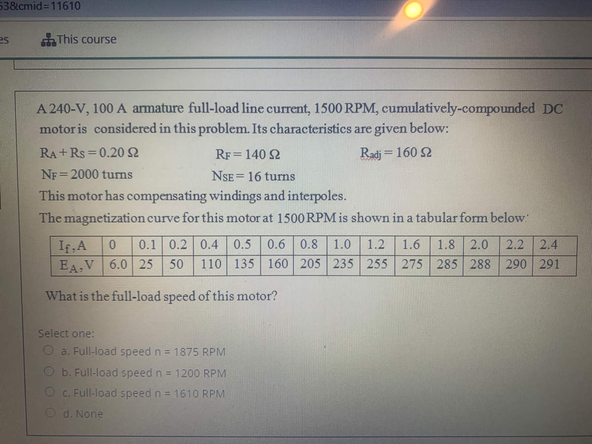
A 240-V, 100 A armature full-load line current, 1500 RPM, cumulatively-compounded DC
motor is considered in this problem. Its characteristics are given below:
RA +Rs = 0.20 2
RF= 140 2
Radj = 160 2
NF =2000 turns
NSE= 16 turns
!!
This motor has compensating windings and interpoles.
The magnetization curve for this motor at 1500 RPM is shown in a tabular form below
0.1 0.2
If A
EA.V 6.0 25
0.4
0.5
0.6
0.8
1.0
1.2
1.6
1.8
2.0
2.2
2.4
50
110
135 160 205 235 255 275
285 288
290 291
What is the full-load speed of this motor?
Select one:
a. Full-load speed n = 1875 RPM
b. Full-load speed n = 1200 RPM
C. Full-load speed n = 161O RPM
d. None
Expert Solution
This question has been solved!
Explore an expertly crafted, step-by-step solution for a thorough understanding of key concepts.

Step by stepSolved in 2 steps with 1 images

Knowledge Booster


Learn more about
Need a deep-dive on the concept behind this application? Look no further. Learn more about this topic, electrical-engineering and related others by exploring similar questions and additional content below.Similar questions
- L-1). The 3-phase wound-rotor induction motor has .... . a) high starting torque b) low starting current c) both "a" and "b" d) neither "a" nor "b" L-2). The 3-phase wound-rotor induction.........a) motor has a wire wound rotor b) motor's rotor can be connected to an external resistive load by way of slip rings and brushes c) motor requires more maintenance than the 3-phase squirrel-cage induction motor d) all of the above L-3). The 3-phase wound-rotor induction motor's rotor circuit's resistance should be adjusted so it is__________ during starting. a) low b) high c) either "a" or "b" d) neither "a" nor "b" L-4). Will a 3-phase wound-rotor induction motor start with no external circuit connected to its rotor leads? a) yes b) noarrow_forwardThe schematic and torque-speed characteristics of a series wound DC motor are shown below : Field winding DC Supply Eb speed Torque - T-K, I, Field Flux = ø = Kla (i) According to the equations given above, explain why the torque of the series-wound DC motor is so high at low speed. Give application examples that require such torque-speed characteristics. A series-wound DC motor should never be started with light or NO LOAD. Give reason. (ii) (iii) Armature anbioarrow_forwardA 3 phase, 1500 rpm, 2200 V, star connected synchronous motor has an impedance of 0.4+j90 per phase. At some excitation 2900 V is induced in the armature. Find the maximum torque developed by motor before the motor breaks out of synchronism. Also find the load angle this time.arrow_forward
- 8) A 230 V fed single quadrant chopper has a 40% duty cycle. A separately excited DC motor is controlled by a chopper. Motor has a back emf constant of 0.5 V/rad/s and 2 22 armature resistance. Determine the torque of motor at speed of 1400 rpm 4.7 N-m 15.44 N-m 10.5 N-m 19 N-marrow_forwardone hour u have answer pleasearrow_forwardA value of magnetizing current in a 3-phase induction motor * gives power factor smaller .. larger smaller. .poor large . better O large...poor Oarrow_forward
- A 100-V series motor is used to drive a load through a pulley. This machine has anarmature resistance of 0.2 ohm and a series-field resistance of 0.25 ohm. When atorque of 25 N-m is applied to the pulley, the speed is 600 rpm. If SPL at this load is300 W, calculate the armature current.arrow_forwardQUESTION 2 a) Draw the equivalent circuit and torque-speed characteristic curve for a series DC motor. b) Briefly explain the induced torque occurs in a series DC motor. e) A 20-hp 240-V 76-A 900 rimin series motor has a field winding of 33 turns per pole. Its armature resistance is 0.09 2, and its field resistance is 0.06 2. The magnetization curve expressed in terms of magnetomotive force versus Ex at 900 rimin is given by the following table: Table Q2 c): The magnetomotive force table for a de motor taken at 900r'min E. V 95 150 188 212 229 243 F.A tuus 1000 1500 2000 2500 500 3000 If the motor running at 33 percent of the full-koad armature current, determine: ) The motor's power converted from electrical to mechanical form, Prene i) The motor's torque, Tnit ii) The motor's speed, narrow_forward. Explain how the pulsating mmf of a single-phase induction motor may be considered equivalent to two oppositely-rotating fields. Develop an expression for the torque of the motor. A 125-W, 4-pole, 110-V, 50-Hz single-phase induction motor has the no-load rotational loss of 25 watts and total rotor copper loss at rated load of 25 watts at a slip of 0.06. At a slip s = 0.06, what is the power input to the machine ?arrow_forward
- Question 3: Answer the following question below: a. Consider a permanent-magnet de motor with the following parameters: R-0.4ohm, L.-1 mH, kE-0.4 V/(rad/s), kr=0.4 Nm/A, and J-0.03 kg m. The rated torque of this motor is 5 Nm. Plot the steady state torque-speed characteristics for V.-60 V b. The motor in (a) is driving a load whose torque requirement remains constant at 5 Nm, independent of speed. Calculate the armature voltage V. to be applied in steady state, if this load is to be driven at 1,800 rpm. c. In an ECM drive, kg-kr-0.8 in SI units. Plot the phase currents and the induced-emf waveforms, as a function of 5, if the motor is operating at a speed of 150 rad/s and delivering a torque of 7 Nm.arrow_forward200 +21. If maximum torque of an induction motor is kg-m at a slip of 12%, the torque at 6% slip would be...... kg-m. 1 (a) 100 (b) 160 (c) 50 (d) 40 B, 1993)arrow_forwardPlease answer questions and please ensure each answer is labeledarrow_forward
arrow_back_ios
SEE MORE QUESTIONS
arrow_forward_ios
Recommended textbooks for you
- Introductory Circuit Analysis (13th Edition)Electrical EngineeringISBN:9780133923605Author:Robert L. BoylestadPublisher:PEARSON
 Delmar's Standard Textbook Of ElectricityElectrical EngineeringISBN:9781337900348Author:Stephen L. HermanPublisher:Cengage Learning
 Programmable Logic ControllersElectrical EngineeringISBN:9780073373843Author:Frank D. PetruzellaPublisher:McGraw-Hill Education
  Fundamentals of Electric CircuitsElectrical EngineeringISBN:9780078028229Author:Charles K Alexander, Matthew SadikuPublisher:McGraw-Hill Education
 Electric Circuits. (11th Edition)Electrical EngineeringISBN:9780134746968Author:James W. Nilsson, Susan RiedelPublisher:PEARSON
 Engineering ElectromagneticsElectrical EngineeringISBN:9780078028151Author:Hayt, William H. (william Hart), Jr, BUCK, John A.Publisher:Mcgraw-hill Education,
Introductory Circuit Analysis (13th Edition)
Electrical Engineering
ISBN:9780133923605
Author:Robert L. Boylestad
Publisher:PEARSON
Delmar's Standard Textbook Of Electricity
Electrical Engineering
ISBN:9781337900348
Author:Stephen L. Herman
Publisher:Cengage Learning
Programmable Logic Controllers
Electrical Engineering
ISBN:9780073373843
Author:Frank D. Petruzella
Publisher:McGraw-Hill Education
Fundamentals of Electric Circuits
Electrical Engineering
ISBN:9780078028229
Author:Charles K Alexander, Matthew Sadiku
Publisher:McGraw-Hill Education
Electric Circuits. (11th Edition)
Electrical Engineering
ISBN:9780134746968
Author:James W. Nilsson, Susan Riedel
Publisher:PEARSON
Engineering Electromagnetics
Electrical Engineering
ISBN:9780078028151
Author:Hayt, William H. (william Hart), Jr, BUCK, John A.
Publisher:Mcgraw-hill Education,