Power System Analysis and Design (MindTap Course List)
6th Edition
ISBN: 9781305632134
Author: J. Duncan Glover, Thomas Overbye, Mulukutla S. Sarma
Publisher: Cengage Learning
expand_more
expand_more
format_list_bulleted
Question
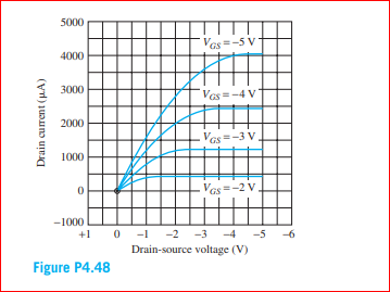
The output characteristics for a PMOS transistor. What are the values of Kp and VTP for this transistor? Is this an enhancement-mode
or depletion-mode transistor? What is the value of
W/L for this device?

Transcribed Image Text:5000
Vas=-5 V
4000
3000
Vas=-4 V
2000
Vas=-3 V
1000
Vas =-2 V
-1000
+1 0 -1 -2 -3 -4 -5 -6
Drain-source voltage (V)
Figure P4.48
Drain current (HA)
Expert Solution
This question has been solved!
Explore an expertly crafted, step-by-step solution for a thorough understanding of key concepts.
Step by stepSolved in 4 steps with 7 images

Knowledge Booster
Learn more about
Need a deep-dive on the concept behind this application? Look no further. Learn more about this topic, electrical-engineering and related others by exploring similar questions and additional content below.Similar questions
- 2.0 a. TMP35 b. TMP36 c. TMP37 +Vs - 3V Using the appropriate curve, develop a linear equation for the output temperature as a function of voltage. 1.8 1.6 E 1.4 1.2 1.0 0.8 0.6 0.4 0.2 -50 -25 25 50 75 100 125 TEMPERATURE (*C) Figure 6. Output Voltage vs. Temperature OUTPUT VOLTAGE (V) 200-20C 00arrow_forwardPlease show step by step working with neat sketch of the graph thank you.(please handwrite solutions)arrow_forwardHow you have find the value of k, Pls expalin in detailarrow_forward
- Find the value of IC given that VC = 12 V. Express your answer in kohms. %3D VCC 18V ER1 <4.7kO 5.6k0 31.2koarrow_forwardDetermine the approximate value of VGG of Figure 522. VDD T17V 21.8kQ V, = 9.8V %3D Q1 1MQ pss 9mA DSS V. V =-4.5V EVGG Figure 522. O-1.2 V -3.281 V O 1.453 V -1.5 Varrow_forward5 V R1 R2 R3 D1 D2 D3 Vout R4 R5 R6 -5 V Given: • Diode voltage = 1 V • R1 = 6.3 kOhm • R2 = 7.2 kOhm • R3 = 6.5 kOhm • R4 = 4.2 kOhm • R5 = 2.1 kOhm • R6 = 2.4 kOhm What is the voltage at Vout (in V)? Answer tolerance is 5%.arrow_forward
- OCX elp VCC VEE 6V 3V R2 A R1 2kQ 2kQ R5 2kQ a) Find the voltage at point A due to VCC only. b) Find the voltage at point A due to VEE only. c) Find the voltage at point A when both are activated.arrow_forwardB.. What is the load current for the circuit shown in the figure? Please choose one: a. 6.0 mA b. 3.0 mA C. 9.0 mA D. 7.5 mAarrow_forwardBasic Electrical EngineeringDraw symbols of electrical components. Note: You may use both IEC and NEMA symbols. - Conductors crossing but not connected- Conductors crossing and connected - DC source other than battery- DC generator- AC voltage source- Ideal current source- Ideal Voltage Source- Current Controlled Current Source- Current Controlled Voltage Source- Voltage Controlled Current Source - Voltage Controlled Voltage Sourcearrow_forward
arrow_back_ios
SEE MORE QUESTIONS
arrow_forward_ios
Recommended textbooks for you
 Power System Analysis and Design (MindTap Course ...Electrical EngineeringISBN:9781305632134Author:J. Duncan Glover, Thomas Overbye, Mulukutla S. SarmaPublisher:Cengage Learning

Power System Analysis and Design (MindTap Course ...
Electrical Engineering
ISBN:9781305632134
Author:J. Duncan Glover, Thomas Overbye, Mulukutla S. Sarma
Publisher:Cengage Learning