
Introductory Circuit Analysis (13th Edition)
13th Edition
ISBN: 9780133923605
Author: Robert L. Boylestad
Publisher: PEARSON
expand_more
expand_more
format_list_bulleted
Related questions
Question
The frequency of the sinusoidal voltage source
in the circuit is adjusted until the current io is in phase with
vg.
1. Find the frequency in hertz.
2. Find the steady-state expression for ig (at the frequency found in
[a]) if vg=90 cosωt V.
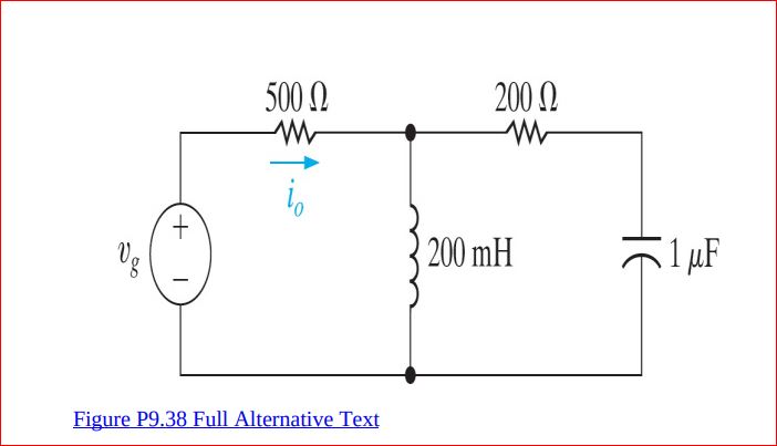

Transcribed Image Text:500 N
200 N
+.
200 mH
1 µF
Figure P9.38 Full Alternative Text
HE
Expert Solution
This question has been solved!
Explore an expertly crafted, step-by-step solution for a thorough understanding of key concepts.

This is a popular solution

Trending nowThis is a popular solution!

Step by stepSolved in 5 steps

Knowledge Booster


Learn more about
Need a deep-dive on the concept behind this application? Look no further. Learn more about this topic, electrical-engineering and related others by exploring similar questions and additional content below.Similar questions
- A sinusoidal voltage is zero at t= -2ms and increasing at a rate of 80000. The maximum amplitude of the voltage is 80V. (a) What is the frequency of v in radians per second? (b) What is the expression for u(t)?arrow_forwardFind the RMS value of the waveform depicted below. Given A = 5, a = 2, b = 6, and T = 13 Hint: You will probably want to express the waveform as a piecewise function. A www a+b T 2T t=a t=b 0 tarrow_forward4. The waveform of a sinusoidal voltage is shown as Vin(t) 2V -2V+ (a) Determine the equation of the sinusoidal voltage. (Note that the unit of time is in milliseconds) (b) If the sinusoidal voltage is applied on a 1022, determine the power dissipated by the resistor. 14 t, ms (c) Determine the time in the first cycle at which the value sinusoidal voltage is 0.6V. (c) Draw the waveform of VD(t) and Vr(t) if the sinusoidal voltage is applied as input to a diode circuit as shown. Use ideal diode approximation. Vin D IDarrow_forward
- R + 12 cos 3t V Vo 4 sin 2t A 10 V If we would like to use Superposition to solve for v, in the circuit shown above, we must find the individual contribution of .each independent source :SINUSOIDAL CURRENT SOURCE CONTRIBUTION What is the amplitude of the voltage v, considering only the contribution of the sinusoidal current source? Assume that R = .15 Ohms, L = 11.6 Henry, and C = 0.02 Farad .Write your answer in Voltsarrow_forwardPower in Extreme Frequency Limits. You and your team have been assigned to find a power supply for the circuit in the drawing. which can be used to supply a dc voltage at 15.0 V, or a high frequency ac signal with a root-mean-square (rms) voltage of 15.0 V. The components in the circuit have the following values: R=4.600, C= 20 nF, and L = 22 mH. Your task is to estimate the peak wattage (i.e.. power) required of the power supply for (a) the dc and (b) the high frequency signals. Conceptual Example 5 will provide insight into this problem. (a) Number (b) Number 24.4 196 R ww Units W Units W C HH elle L Rarrow_forward
arrow_back_ios
arrow_forward_ios
Recommended textbooks for you
- Introductory Circuit Analysis (13th Edition)Electrical EngineeringISBN:9780133923605Author:Robert L. BoylestadPublisher:PEARSON
 Delmar's Standard Textbook Of ElectricityElectrical EngineeringISBN:9781337900348Author:Stephen L. HermanPublisher:Cengage Learning
 Programmable Logic ControllersElectrical EngineeringISBN:9780073373843Author:Frank D. PetruzellaPublisher:McGraw-Hill Education
  Fundamentals of Electric CircuitsElectrical EngineeringISBN:9780078028229Author:Charles K Alexander, Matthew SadikuPublisher:McGraw-Hill Education
 Electric Circuits. (11th Edition)Electrical EngineeringISBN:9780134746968Author:James W. Nilsson, Susan RiedelPublisher:PEARSON
 Engineering ElectromagneticsElectrical EngineeringISBN:9780078028151Author:Hayt, William H. (william Hart), Jr, BUCK, John A.Publisher:Mcgraw-hill Education,
Introductory Circuit Analysis (13th Edition)
Electrical Engineering
ISBN:9780133923605
Author:Robert L. Boylestad
Publisher:PEARSON
Delmar's Standard Textbook Of Electricity
Electrical Engineering
ISBN:9781337900348
Author:Stephen L. Herman
Publisher:Cengage Learning
Programmable Logic Controllers
Electrical Engineering
ISBN:9780073373843
Author:Frank D. Petruzella
Publisher:McGraw-Hill Education
Fundamentals of Electric Circuits
Electrical Engineering
ISBN:9780078028229
Author:Charles K Alexander, Matthew Sadiku
Publisher:McGraw-Hill Education
Electric Circuits. (11th Edition)
Electrical Engineering
ISBN:9780134746968
Author:James W. Nilsson, Susan Riedel
Publisher:PEARSON
Engineering Electromagnetics
Electrical Engineering
ISBN:9780078028151
Author:Hayt, William H. (william Hart), Jr, BUCK, John A.
Publisher:Mcgraw-hill Education,