Elements Of Electromagnetics
7th Edition
ISBN: 9780190698614
Author: Sadiku, Matthew N. O.
Publisher: Oxford University Press
expand_more
expand_more
format_list_bulleted
Question

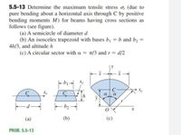
Transcribed Image Text:5.5-13 Determine the maximum tensile stress o, (due to
pure bending about a horizontal axis through C by positive
bending moments M) for beams having cross sections as
follows (see figure).
(a) A semicircle of diameter d
(b) An isosceles trapezoid with bases bị = b and bɔ =
4b/3, and altitude h
(c) A circular sector with a = 1/3 and r = d/2
C
C
a
a
(a)
(b)
PROB. 5.5-13
Expert Solution
This question has been solved!
Explore an expertly crafted, step-by-step solution for a thorough understanding of key concepts.
Step by stepSolved in 4 steps with 4 images

Knowledge Booster
Learn more about
Need a deep-dive on the concept behind this application? Look no further. Learn more about this topic, mechanical-engineering and related others by exploring similar questions and additional content below.Similar questions
- A cantilever beam AB, loaded by a uniform load and a concentrated load (see figure), is constructed of a channel section. 250 lb 22.5 lb/ft A 5.0 ft 3.0 ft- 0.617 in. 2.269 in. (a) Find the maximum tensile stress o, (in psi) and maximum compressive stress o, (in psi) if the cross section has the dimensions indicated and the moment of inertia about the z-axis (the neutral axis) is I = 3.10 in4. Note: The uniform load represents the weight of the beam. (Use the deformation sign convention.) O, = psi psi (b) Find the maximum value of the concentrated load (in Ib) if the maximum tensile stress cannot exceed 4 ksi and the maximum compressive stress is limited to 18.0 ksi. (Enter the magnitude.) Ib (c) How far from A (in ft) can load P = 250 lb be positioned if the maximum tensile stress cannot exceed 4 ksi and the maximum compressive stress is limited to 18.0 ksi? ftarrow_forwardQ3) A circular bar of 25mm diameter is formed into a semicircular arch and loaded as shown in the figure. Determine the maximum bending stress. Assume that the flexure formula for straight beams is applicable. 200KN 100KN R=1.5m 230°arrow_forwardDuring construction of a highway bridge, the main girders are cantilevered outward from one pier toward the next (see figure). Each girder hasa cantilever length of 48 m and an I-shaped cross section with dimensions shown in the figure. The load on each girder (during construction) is assumed to be 9.5 kN/m, which includes the weight of the girder. Determine the maximum bending stress in a girder due to this load.arrow_forward
arrow_back_ios
arrow_forward_ios
Recommended textbooks for you
 Elements Of ElectromagneticsMechanical EngineeringISBN:9780190698614Author:Sadiku, Matthew N. O.Publisher:Oxford University Press
 Mechanics of Materials (10th Edition)Mechanical EngineeringISBN:9780134319650Author:Russell C. HibbelerPublisher:PEARSON
 Thermodynamics: An Engineering ApproachMechanical EngineeringISBN:9781259822674Author:Yunus A. Cengel Dr., Michael A. BolesPublisher:McGraw-Hill Education
 Control Systems EngineeringMechanical EngineeringISBN:9781118170519Author:Norman S. NisePublisher:WILEY
 Mechanics of Materials (MindTap Course List)Mechanical EngineeringISBN:9781337093347Author:Barry J. Goodno, James M. GerePublisher:Cengage Learning
 Engineering Mechanics: StaticsMechanical EngineeringISBN:9781118807330Author:James L. Meriam, L. G. Kraige, J. N. BoltonPublisher:WILEY

Elements Of Electromagnetics
Mechanical Engineering
ISBN:9780190698614
Author:Sadiku, Matthew N. O.
Publisher:Oxford University Press

Mechanics of Materials (10th Edition)
Mechanical Engineering
ISBN:9780134319650
Author:Russell C. Hibbeler
Publisher:PEARSON

Thermodynamics: An Engineering Approach
Mechanical Engineering
ISBN:9781259822674
Author:Yunus A. Cengel Dr., Michael A. Boles
Publisher:McGraw-Hill Education

Control Systems Engineering
Mechanical Engineering
ISBN:9781118170519
Author:Norman S. Nise
Publisher:WILEY

Mechanics of Materials (MindTap Course List)
Mechanical Engineering
ISBN:9781337093347
Author:Barry J. Goodno, James M. Gere
Publisher:Cengage Learning

Engineering Mechanics: Statics
Mechanical Engineering
ISBN:9781118807330
Author:James L. Meriam, L. G. Kraige, J. N. Bolton
Publisher:WILEY