Introductory Circuit Analysis (13th Edition)
13th Edition
ISBN: 9780133923605
Author: Robert L. Boylestad
Publisher: PEARSON
expand_more
expand_more
format_list_bulleted
Concept explainers
Question
Pen paper solution please

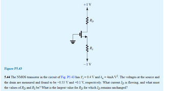
Transcribed Image Text:+1 V
www
RD
Rs
-1 V
Figure P5.43
5.44 The NMOS transistor in the circuit of Fig. P5.43 has V₂ = 0.4 V and k, = 4mA/V². The voltages at the source and
the drain are measured and found to be −0.55 V and +0.1 V, respectively. What current ID is flowing, and what must
the values of R₂ and Rs be? What is the largest value for Rp for which I remains unchanged?
Expert Solution
This question has been solved!
Explore an expertly crafted, step-by-step solution for a thorough understanding of key concepts.
This is a popular solution
Trending nowThis is a popular solution!
Step by stepSolved in 4 steps with 1 images

Knowledge Booster
Learn more about
Need a deep-dive on the concept behind this application? Look no further. Learn more about this topic, electrical-engineering and related others by exploring similar questions and additional content below.Similar questions
- In CB configuration, the value of a=0.98A. A voltage drop of 4.9V is obtained across the resistor of 5KQ when connected in collector circuit. Find the base current. a) 0.01mA b) 0.07MA c) 0.02mA d) 0.05mAarrow_forwardA particular MOSFET has VA = 10 V. For operation at 10 μA and 100 μA, what are the expected resistances? In each case, for a change in vDS of 1 V, what percentage change in drain current would you expect?arrow_forward2. An NMOS transistor, operating in the linear resistance region, with VDS = 50 mV, is found to conduct 25 uA for VGS-1V and 50 uA for VGs 1.5V. a. What is the apparent value of the threshold voltage V₂? If kn= 50 uA/V2, what is the device W/L ratio? b. c. What current could you expect to flow with VGS = 2V and VDS=0.1V? d. If the device is operated what VGs=2V, at what value of VDs will the drain end of the MOSFET channel just reach pinch-off, and what is the corresponding drain current?arrow_forward
- Please answer in typing format please ASAP for the like please clear the solution of above question is given to Please answer in typing format please ASAP for the like pleasearrow_forwardD5.48 The PMOS transistor in the circuit of Fig. P5.48 has V; = -0.5 V, µ„Cox = 100 µA/V², L = 0.18 µm, and 2 = 0. Find the values required for W and R in order to establish a drain current of 160 µA and a voltage Vp of 0.8 V. VDp = 1.8 V o VD Rarrow_forwardPlease answer in typing formatarrow_forward
- Given a depletion-type MOSFET with IDSS = 6 mA and VP = -3 V, determine the drain current at VGS = -1, 0, 1, and 2 V. Compare the difference in current levels between -1 V and 0 V with the difference between 1 V and 2 V. In the positive VGS region, does the drain current increase at a significantly higher rate than for negative values? Does the ID curve become more and more vertical with increasing positive values of VGS? Is there a linear or a nonlinear relationship between ID and VGS? Explain.arrow_forwardQ25 In a N-Channel JFET if the voltage across the drain and source (VDDS) is increased then explain in detail with neat diagram the changes in drain current. Justify your answer. ii) The reverse gate voltage of JFET when changes from 3.5 V to 3.2 V, the drain current changes from 1.2 mA to 2.1 mA. Calculate the value of transconductance of the transistor.arrow_forwardSolve the related problems in this examples.arrow_forward
- Problem 1. Suppose the body electrode of a MOSFET with a p-Si body is at ground potential, and the gate voltage, VG, is set appropriately to create an inversion channel between the source and drain electrodes. Which electrode, the Source or the Drain, will need a more positive potential if we wanted to move channel carriers from the Drain towards the Source (as opposed to the normal flow direction of Source to Drain)? As always required on your work, explain your answer.arrow_forward4. For the circuit given below, determine the voltage (VBB) that just lets the transistor go into saturation. Assume the VCE is equal to 0.3V when the transistor goes into saturation. Assume current gain hfE = 200. The transistor is silicon type (i.e., VBE is 0.7V) + 10V (Vcc) VBB Rc32 k2 Ic 50 k2 SRB IB VBEarrow_forwardKindly answer the following question (as soon as possible) #24arrow_forward
arrow_back_ios
SEE MORE QUESTIONS
arrow_forward_ios
Recommended textbooks for you
 Introductory Circuit Analysis (13th Edition)Electrical EngineeringISBN:9780133923605Author:Robert L. BoylestadPublisher:PEARSON
 Delmar's Standard Textbook Of ElectricityElectrical EngineeringISBN:9781337900348Author:Stephen L. HermanPublisher:Cengage Learning
 Programmable Logic ControllersElectrical EngineeringISBN:9780073373843Author:Frank D. PetruzellaPublisher:McGraw-Hill Education
 Fundamentals of Electric CircuitsElectrical EngineeringISBN:9780078028229Author:Charles K Alexander, Matthew SadikuPublisher:McGraw-Hill Education
 Electric Circuits. (11th Edition)Electrical EngineeringISBN:9780134746968Author:James W. Nilsson, Susan RiedelPublisher:PEARSON
 Engineering ElectromagneticsElectrical EngineeringISBN:9780078028151Author:Hayt, William H. (william Hart), Jr, BUCK, John A.Publisher:Mcgraw-hill Education,

Introductory Circuit Analysis (13th Edition)
Electrical Engineering
ISBN:9780133923605
Author:Robert L. Boylestad
Publisher:PEARSON

Delmar's Standard Textbook Of Electricity
Electrical Engineering
ISBN:9781337900348
Author:Stephen L. Herman
Publisher:Cengage Learning

Programmable Logic Controllers
Electrical Engineering
ISBN:9780073373843
Author:Frank D. Petruzella
Publisher:McGraw-Hill Education

Fundamentals of Electric Circuits
Electrical Engineering
ISBN:9780078028229
Author:Charles K Alexander, Matthew Sadiku
Publisher:McGraw-Hill Education

Electric Circuits. (11th Edition)
Electrical Engineering
ISBN:9780134746968
Author:James W. Nilsson, Susan Riedel
Publisher:PEARSON

Engineering Electromagnetics
Electrical Engineering
ISBN:9780078028151
Author:Hayt, William H. (william Hart), Jr, BUCK, John A.
Publisher:Mcgraw-hill Education,