Introductory Circuit Analysis (13th Edition)
13th Edition
ISBN: 9780133923605
Author: Robert L. Boylestad
Publisher: PEARSON
expand_more
expand_more
format_list_bulleted
Question

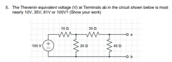
Transcribed Image Text:**Thevenin Equivalent Voltage Calculation**
**Problem Statement:**
Determine the Thevenin equivalent voltage (V) at terminals ab in the circuit shown below. The possible values are 10V, 35V, 61V, or 100V. (Show your work.)
**Circuit Description:**
- A voltage source of 100V is connected to three resistors in a linear arrangement.
- Resistor R1 = 10Ω is connected in series with Resistor R2 = 30Ω.
- These two resistors are then connected parallel to Resistor R3 = 20Ω.
- Another resistor, R4 = 40Ω, is connected at terminal 'a' across 'b'.
**Approach to Solve:**
1. **Circuit Analysis:**
- Identify the part of the circuit that affects the Thevenin equivalent seen from terminals a and b.
- Use series and parallel resistor combinations to simplify the circuit step by step.
2. **Thevenin Voltage Calculation:**
- Use voltage divider rules and parallel combination rules for the resistors to find the open circuit voltage at the terminals a-b.
3. **Calculate:**
- Solve the equations based on the above simplifications to arrive at the Thevenin voltage.
By following these steps, you would calculate the precise Thevenin voltage for terminals ab which will be one of the provided options (10V, 35V, 61V, or 100V).
Expert Solution
This question has been solved!
Explore an expertly crafted, step-by-step solution for a thorough understanding of key concepts.
Step by stepSolved in 3 steps with 3 images

Knowledge Booster
Learn more about
Need a deep-dive on the concept behind this application? Look no further. Learn more about this topic, electrical-engineering and related others by exploring similar questions and additional content below.Similar questions
- 5 From the following circuit, compute the total current. Express your result as IT=1500.67mA V4 — 400V R12 www 4ΚΩ R15 ww 6ΚΩ R13 •4ΚΩ R14 Μ 4ΚΩarrow_forwardProblem 1 - For the circuit below, determine the voltages across C₁ and C₂ and the currents through L₁, L2 and L3 under D.C. conditions. (Note: There is no switching and all conditions have been going for a while.) 2 ΚΩ L3= 1 mH m L2 = 0.5 mH L₁ = 0.2 mH C₁ = 10 μF + 4 ΚΩ 6 kQ C₂=4 μF 24 Varrow_forwardGiven the Fourier Transform of m(t) is M(f): (a) Write down the Fourier Transform of m(t) cos(2πfet). (b) Write down and simplify the Fourier Transform of m(t) cos(2лft) + jm(t) sin(2πfct).arrow_forward
- 4. Given the following circuit, solve for Vx. Must use source transformation. 6V ( 2 ΚΩ 2 2 ΚΩ + Vx 4 ΚΩ ww Vx 4 ΚΩ (1) 181 Varrow_forward(4) Determine ID in this circuit if VDs = 1V. . SHOW YOUR WORK. 3kQ 10V M V₁ = 0.5V kn' = 0.5mA/V² W/L = 10 10V TOM 2 RD O 0 mA (in cutoff) O 45 mA O 226 MA O 45 A O other/none of the abovearrow_forwardUse nodal Analysis to find v(o) in the following circuit of 6 = 4 krad/s 30V ww 50 sun and A 41023 6 μF 60 mH 20 coswt A 8 karrow_forward
arrow_back_ios
arrow_forward_ios
Recommended textbooks for you
 Introductory Circuit Analysis (13th Edition)Electrical EngineeringISBN:9780133923605Author:Robert L. BoylestadPublisher:PEARSON
 Delmar's Standard Textbook Of ElectricityElectrical EngineeringISBN:9781337900348Author:Stephen L. HermanPublisher:Cengage Learning
 Programmable Logic ControllersElectrical EngineeringISBN:9780073373843Author:Frank D. PetruzellaPublisher:McGraw-Hill Education
 Fundamentals of Electric CircuitsElectrical EngineeringISBN:9780078028229Author:Charles K Alexander, Matthew SadikuPublisher:McGraw-Hill Education
 Electric Circuits. (11th Edition)Electrical EngineeringISBN:9780134746968Author:James W. Nilsson, Susan RiedelPublisher:PEARSON
 Engineering ElectromagneticsElectrical EngineeringISBN:9780078028151Author:Hayt, William H. (william Hart), Jr, BUCK, John A.Publisher:Mcgraw-hill Education,

Introductory Circuit Analysis (13th Edition)
Electrical Engineering
ISBN:9780133923605
Author:Robert L. Boylestad
Publisher:PEARSON

Delmar's Standard Textbook Of Electricity
Electrical Engineering
ISBN:9781337900348
Author:Stephen L. Herman
Publisher:Cengage Learning

Programmable Logic Controllers
Electrical Engineering
ISBN:9780073373843
Author:Frank D. Petruzella
Publisher:McGraw-Hill Education

Fundamentals of Electric Circuits
Electrical Engineering
ISBN:9780078028229
Author:Charles K Alexander, Matthew Sadiku
Publisher:McGraw-Hill Education

Electric Circuits. (11th Edition)
Electrical Engineering
ISBN:9780134746968
Author:James W. Nilsson, Susan Riedel
Publisher:PEARSON

Engineering Electromagnetics
Electrical Engineering
ISBN:9780078028151
Author:Hayt, William H. (william Hart), Jr, BUCK, John A.
Publisher:Mcgraw-hill Education,