Elements Of Electromagnetics
7th Edition
ISBN: 9780190698614
Author: Sadiku, Matthew N. O.
Publisher: Oxford University Press
expand_more
expand_more
format_list_bulleted
Question
I get a little confused when it is stated "Flow rate is = Ma" Isnt flow rate= Av?

Transcribed Image Text:### Problem Statement
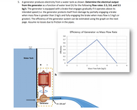
A generator produces electricity from a water tank as shown. Determine the electrical output from the generator as a function of water level (h) for the following flow rates: 2.5, 3.0, and 3.5 kg/s. The generator is equipped with a brake that engages gradually if it operates above its intended speed (i.e., the generator protects itself from damage by partially engaging a brake when mass flow is greater than 3 kg/s and fully engaging the brake when mass flow is 5 kg/s or greater). The efficiency of the generator system can be estimated using the graph on the next page. Assume no losses due to friction in the pipes.
### Diagram Explanation
The diagram shows a setup with a water tank and a generator. Water flows from the tank to the generator, creating electrical output.
- **Water Tank:** The tank provides water that flows through the generator.
- **Generator:** Converts the kinetic energy of water into electrical energy. It is depicted in the system setup.
- **Flow Path:** Water enters the generator through a pipe with a cross-sectional area of 25 cm².
### Graph Explanation
**Efficiency of Generator vs Mass Flow Rate**
- **X-axis:** Mass Flow Rate (kg/s) ranging from 0 to 6 kg/s.
- **Y-axis:** Efficiency ranging from 0 to 0.8.
The graph shows the efficiency of the generator relative to different mass flow rates:
- Efficiency increases linearly, peaking at around 0.75 at a flow rate of 3 kg/s.
- Beyond 3 kg/s, efficiency decreases, reaching 0 when the mass flow rate is at 5 kg/s.
### Application
Use the given information and diagram to calculate the electrical output based on the water level (h) for specified flow rates using the efficiency graph.
Expert Solution
This question has been solved!
Explore an expertly crafted, step-by-step solution for a thorough understanding of key concepts.
This is a popular solution
Trending nowThis is a popular solution!
Step by stepSolved in 4 steps with 4 images

Knowledge Booster
Learn more about
Need a deep-dive on the concept behind this application? Look no further. Learn more about this topic, mechanical-engineering and related others by exploring similar questions and additional content below.Similar questions
Recommended textbooks for you
 Elements Of ElectromagneticsMechanical EngineeringISBN:9780190698614Author:Sadiku, Matthew N. O.Publisher:Oxford University Press
 Mechanics of Materials (10th Edition)Mechanical EngineeringISBN:9780134319650Author:Russell C. HibbelerPublisher:PEARSON
 Thermodynamics: An Engineering ApproachMechanical EngineeringISBN:9781259822674Author:Yunus A. Cengel Dr., Michael A. BolesPublisher:McGraw-Hill Education
 Control Systems EngineeringMechanical EngineeringISBN:9781118170519Author:Norman S. NisePublisher:WILEY
 Mechanics of Materials (MindTap Course List)Mechanical EngineeringISBN:9781337093347Author:Barry J. Goodno, James M. GerePublisher:Cengage Learning
 Engineering Mechanics: StaticsMechanical EngineeringISBN:9781118807330Author:James L. Meriam, L. G. Kraige, J. N. BoltonPublisher:WILEY

Elements Of Electromagnetics
Mechanical Engineering
ISBN:9780190698614
Author:Sadiku, Matthew N. O.
Publisher:Oxford University Press

Mechanics of Materials (10th Edition)
Mechanical Engineering
ISBN:9780134319650
Author:Russell C. Hibbeler
Publisher:PEARSON

Thermodynamics: An Engineering Approach
Mechanical Engineering
ISBN:9781259822674
Author:Yunus A. Cengel Dr., Michael A. Boles
Publisher:McGraw-Hill Education

Control Systems Engineering
Mechanical Engineering
ISBN:9781118170519
Author:Norman S. Nise
Publisher:WILEY

Mechanics of Materials (MindTap Course List)
Mechanical Engineering
ISBN:9781337093347
Author:Barry J. Goodno, James M. Gere
Publisher:Cengage Learning

Engineering Mechanics: Statics
Mechanical Engineering
ISBN:9781118807330
Author:James L. Meriam, L. G. Kraige, J. N. Bolton
Publisher:WILEY