Structural Analysis
6th Edition
ISBN: 9781337630931
Author: KASSIMALI, Aslam.
Publisher: Cengage,
expand_more
expand_more
format_list_bulleted
Question
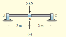
Draw the shear and moment diagrams for the shaft shown.
The support at A is a thrust bearing and the support at C is a journal bearing.

Transcribed Image Text:5 kN
B.
-2 m-
-2 m-
(a)
Expert Solution
This question has been solved!
Explore an expertly crafted, step-by-step solution for a thorough understanding of key concepts.
This is a popular solution
Trending nowThis is a popular solution!
Step by stepSolved in 2 steps with 1 images

Knowledge Booster
Learn more about
Need a deep-dive on the concept behind this application? Look no further. Learn more about this topic, civil-engineering and related others by exploring similar questions and additional content below.Similar questions
- For the frame shown, determine the Horizontal component of the force at E and A. Vertical component of the force at E and A. Internal force at member BD and BC. A E 4' 120 lb B 5' D 3¹ C 4'arrow_forwardA=6 B=2 C=4 D=3 E=6 F=8 Question 3) For the frame shown; a) Determine reaction forces at A and C. (Hand Calculation) b) Draw shear and moment diagrams. (Hand Calculation) c) Verify your results with a structural analysis software. Joint A is fix supported. The support at C is pin. d kN/m bm em a kN omarrow_forwardShow your step by solutionarrow_forward
- 1. From the truss loaded as shown, determine the stress induced on each of the members BC, BD and CD. Consider each member has a cross sectional area of 1200 sq. millimeters. Consider the pulley to be frictionless. Solve the required forces using method of joint and method of sections. 110 kN 5 kN 10 kN 2m 4m 2m E 3m 2m 20KNarrow_forward2arrow_forwardDetermine the maximum positive moment (lbs-ft) in the simply supported beam as shown. Where: Where: L1 = 7ft; L2 = 4.2ft; W = 299lbs/ft W A L1 R₁ B p L2 R₂arrow_forward
- 2-2 A 100-N force is applied at end C of the rod as shown. c) Assess the effect of the angle being varied from 0° to 360° to the moment of the 100-N force about point A. [b) (i) MA=0 N-m; (ii) MA=-24k N-m; (iii) MA=-12k N.m] 2-3 A 600-N force is applied on end D of the bent rod as shown. c) Assess the effect of the angle being varied from 0° to 180° to the moment of the 600-N force about point A. [b) (i) MA= 180 N-m; (ii) MA= - 480k N-m; (iii) MA= 180k N-m; (iv) MA=- 432k N.m] Figure IA Figure 150 mm P2-2 600 N 50 cm B P2-3 90 mm 0 000 B 30 cm C 100 N 30 cmarrow_forward#1arrow_forward
arrow_back_ios
arrow_forward_ios
Recommended textbooks for you

 Structural Analysis (10th Edition)Civil EngineeringISBN:9780134610672Author:Russell C. HibbelerPublisher:PEARSON
 Principles of Foundation Engineering (MindTap Cou...Civil EngineeringISBN:9781337705028Author:Braja M. Das, Nagaratnam SivakuganPublisher:Cengage Learning
 Fundamentals of Structural AnalysisCivil EngineeringISBN:9780073398006Author:Kenneth M. Leet Emeritus, Chia-Ming Uang, Joel LanningPublisher:McGraw-Hill Education
 Traffic and Highway EngineeringCivil EngineeringISBN:9781305156241Author:Garber, Nicholas J.Publisher:Cengage Learning


Structural Analysis (10th Edition)
Civil Engineering
ISBN:9780134610672
Author:Russell C. Hibbeler
Publisher:PEARSON

Principles of Foundation Engineering (MindTap Cou...
Civil Engineering
ISBN:9781337705028
Author:Braja M. Das, Nagaratnam Sivakugan
Publisher:Cengage Learning

Fundamentals of Structural Analysis
Civil Engineering
ISBN:9780073398006
Author:Kenneth M. Leet Emeritus, Chia-Ming Uang, Joel Lanning
Publisher:McGraw-Hill Education


Traffic and Highway Engineering
Civil Engineering
ISBN:9781305156241
Author:Garber, Nicholas J.
Publisher:Cengage Learning