Introductory Circuit Analysis (13th Edition)
13th Edition
ISBN: 9780133923605
Author: Robert L. Boylestad
Publisher: PEARSON
expand_more
expand_more
format_list_bulleted
Question

Transcribed Image Text:2. Design a 3 to 1 multiplexer using min-terms. Sketch your circuit design using only basic gates.

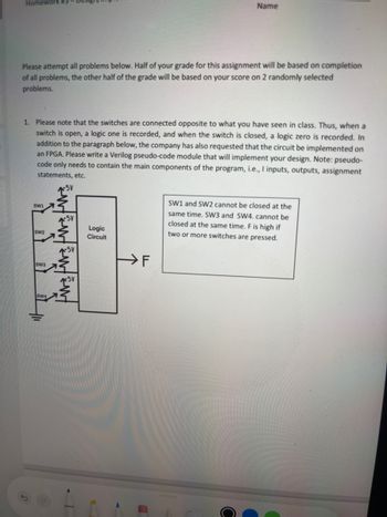
Transcribed Image Text:5
Homework #3
Name
Please attempt all problems below. Half of your grade for this assignment will be based on completion
of all problems, the other half of the grade will be based on your score on 2 randomly selected
problems.
1. Please note that the switches are connected opposite to what you have seen in class. Thus, when a
switch is open, a logic one is recorded, and when the switch is closed, a logic zero is recorded. In
addition to the paragraph below, the company has also requested that the circuit be implemented on
an FPGA. Please write a Verilog pseudo-code module that will implement your design. Note: pseudo-
code only needs to contain the main components of the program, i.e., I inputs, outputs, assignment
statements, etc.
+5V
SW1
SW2
SW3
SW4
fw fw Fwt
Logic
Circuit
F
SW1 and SW2 cannot be closed at the
same time. SW3 and SW4. cannot be
closed at the same time. F is high if
two or more switches are pressed.
Expert Solution
This question has been solved!
Explore an expertly crafted, step-by-step solution for a thorough understanding of key concepts.
Step by stepSolved in 2 steps

Knowledge Booster
Similar questions
- Question 1) If six NOT (inverters) gates are connected in series and the input to the first gate is a LOW (0) the output of the FIFTH. gate will be:arrow_forward2. Design a 3 to 1 multiplexer using min-terms. Sketch your circuit design using only basic gates.arrow_forwardObjectives: To demonstrate the operation, characteristics and design of a saturated bipolar transistor switch Material Needed : 1- 2N2222A NPN transistor 1- 1k ohms resistor 1 - 4.7k ohms resistor 1- 470k ohms resistor ELECTRONIC WORKBENCH Procedure 1. Construct the circuit shown in Fig 1-1. The circuit receives its input from data switch SW1. You will monitor the output at the collector with a voltmeter. +Vcc Rc =1K Vo OUTPUT [SPACEBAR] to switch [Space] Rg=470k VCE SW1 Figure 1-1arrow_forward
- 30) Coils labeled ( S ) and ( R )A) must appear in that order (S before R) in a ladder logic programB) may be used only in subroutines in programs for Siemens PLCsC) are Short and Repeated coils, used in timing programsD) may be used instead of a seal-in arrangement to provide latchingarrow_forwardConstruct a gate circuit using AND, OR, and NOT gates that corresponds one to one with the following switching algebra expression. Assume that inputs are available only in uncomplemented form. (Do not change the expression.) (WX' + Y)[(W + Z)' + (XYZ')]arrow_forwardI need the answer as soon as possiblearrow_forward
arrow_back_ios
arrow_forward_ios
Recommended textbooks for you
 Introductory Circuit Analysis (13th Edition)Electrical EngineeringISBN:9780133923605Author:Robert L. BoylestadPublisher:PEARSON
 Delmar's Standard Textbook Of ElectricityElectrical EngineeringISBN:9781337900348Author:Stephen L. HermanPublisher:Cengage Learning
 Programmable Logic ControllersElectrical EngineeringISBN:9780073373843Author:Frank D. PetruzellaPublisher:McGraw-Hill Education
 Fundamentals of Electric CircuitsElectrical EngineeringISBN:9780078028229Author:Charles K Alexander, Matthew SadikuPublisher:McGraw-Hill Education
 Electric Circuits. (11th Edition)Electrical EngineeringISBN:9780134746968Author:James W. Nilsson, Susan RiedelPublisher:PEARSON
 Engineering ElectromagneticsElectrical EngineeringISBN:9780078028151Author:Hayt, William H. (william Hart), Jr, BUCK, John A.Publisher:Mcgraw-hill Education,

Introductory Circuit Analysis (13th Edition)
Electrical Engineering
ISBN:9780133923605
Author:Robert L. Boylestad
Publisher:PEARSON

Delmar's Standard Textbook Of Electricity
Electrical Engineering
ISBN:9781337900348
Author:Stephen L. Herman
Publisher:Cengage Learning

Programmable Logic Controllers
Electrical Engineering
ISBN:9780073373843
Author:Frank D. Petruzella
Publisher:McGraw-Hill Education

Fundamentals of Electric Circuits
Electrical Engineering
ISBN:9780078028229
Author:Charles K Alexander, Matthew Sadiku
Publisher:McGraw-Hill Education

Electric Circuits. (11th Edition)
Electrical Engineering
ISBN:9780134746968
Author:James W. Nilsson, Susan Riedel
Publisher:PEARSON

Engineering Electromagnetics
Electrical Engineering
ISBN:9780078028151
Author:Hayt, William H. (william Hart), Jr, BUCK, John A.
Publisher:Mcgraw-hill Education,