
Elements Of Electromagnetics
7th Edition
ISBN: 9780190698614
Author: Sadiku, Matthew N. O.
Publisher: Oxford University Press
expand_more
expand_more
format_list_bulleted
Related questions
Question
thumb_up100%

Transcribed Image Text:**Diagram Explanation:**
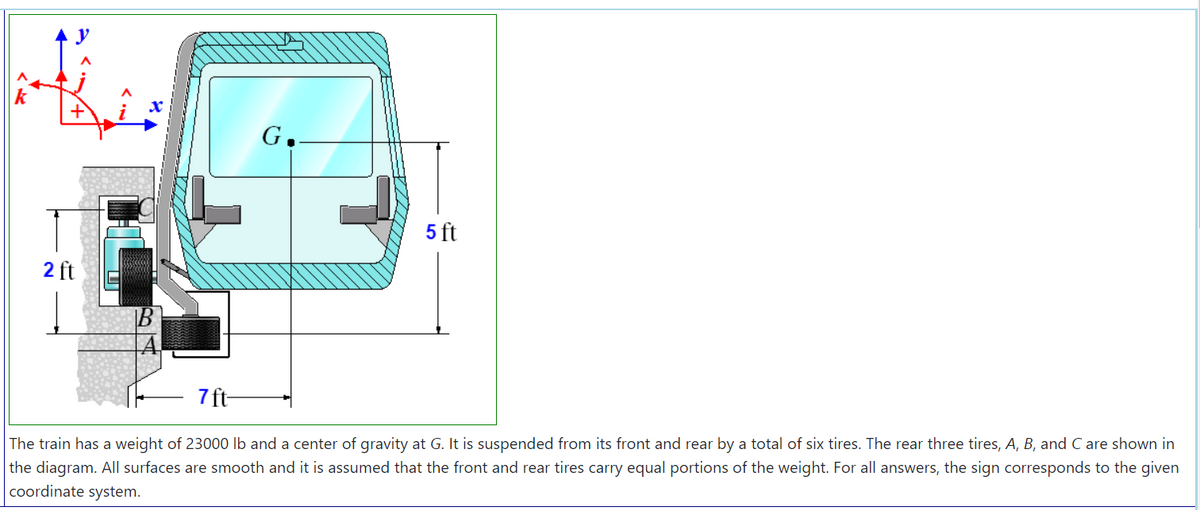
The diagram illustrates a section of a train shown in cross-section with a coordinate system indicating the xyz axes. The train has:
- A total weight of 23,000 lb and the center of gravity located at point G.
- The train is balanced on six tires, with the rear three tires labeled as A, B, and C, depicted in the diagram.
- Dimensions indicated show the vertical distance from the bottom of the train to the center of gravity (G) as 5 feet, and the horizontal distance from the center of gravity to the rear tires as 7 feet.
- A structural component near the rear tires is marked as being 2 feet high.
The surfaces supporting the train are smooth. It is assumed for calculations that the distribution of weight between the front and rear tires is equal. The coordinate system is clearly defined, with the positive x, y, and z directions denoted.
**Text:**
The train has a weight of 23,000 lb and a center of gravity at G. It is suspended from its front and rear by a total of six tires. The rear three tires, A, B, and C are shown in the diagram. All surfaces are smooth and it is assumed that the front and rear tires carry equal portions of the weight. For all answers, the sign corresponds to the given coordinate system.
![```plaintext
| Part | Description | Answer |
|-------|----------------------------|------------|
| A. | The force (lb) on tire A is? | [ ] |
| B. | The force (lb) on tire B is? | [ ] |
| C. | The force (lb) on tire C is? | [ ] |
```
The table includes three parts, each asking for the force in pounds (lb) on a specific tire, labeled A, B, and C. Each part has a corresponding blank space for providing the answer.](https://content.bartleby.com/qna-images/question/98eabd66-347c-4504-bb01-99b451e932fa/546d2e3d-fbd4-41b9-9a4d-21ae5389448a/i6h2k7j_processed.png)
Transcribed Image Text:```plaintext
| Part | Description | Answer |
|-------|----------------------------|------------|
| A. | The force (lb) on tire A is? | [ ] |
| B. | The force (lb) on tire B is? | [ ] |
| C. | The force (lb) on tire C is? | [ ] |
```
The table includes three parts, each asking for the force in pounds (lb) on a specific tire, labeled A, B, and C. Each part has a corresponding blank space for providing the answer.
Expert Solution
This question has been solved!
Explore an expertly crafted, step-by-step solution for a thorough understanding of key concepts.

This is a popular solution

Trending nowThis is a popular solution!

Step by stepSolved in 4 steps with 1 images

Knowledge Booster

Similar questions
- Calculate the magnitude and direction of the resultant force in this system, and it's location with respect to point A?arrow_forwardConsider the pipe structure projecting from the wall at point “A”. Find the resultant force and couple moment acting at point “A”. Express the resultant force and couple moment in Cartesian (vector) form. (Hint: the 1,000 lb force needs to be expressed as a vector and the “dimension box” provides the information necessary to define the unit vector in the direction of F.)arrow_forward1. Determine the horizontal and vertical components of the resultant force applied to the eye bolt. Show your calculation steps. ETE BOLT A= 300 Ibs B= 200 lbsarrow_forward
- Problem 3: Let P' (mass 4 m) be an attracting particle acting on the system S. The system S is comprised of the 4 colored particles: â₂ â₁ S1 S₁ S2 S3 S4 P' mass = 2.5 m 2 m 3 m 6m mass= 4 m mass= Then, the system S possesses the following characteristics where the distance of each particle relative to P'is given: mass= S3 mass= S₂ 70₁4 dâ₁-2dâ₂ = 70 7-0 = 11da₁-10d â₂ = 6 dâ₁-5d â₂ 70→² = 14 dâ₁ +5dâ₂ 70 = 15 dâ₁-8 dâ₂ S4 OParrow_forward4. Find the force on one side of a parabolic plane segment of base 8 ft. and altitude 4 ft. when the segment is submerged vertically in water with its base horizontal, and the base and vertex are 4 ft. and 8 ft. under the surface, respectively. Note: Put the surface of the water along the x - axis.arrow_forwardIn the attached photo, the 3-wheeled cart weighs 120 lbs. If it is loaded as shown with a crate weighing 200 lbs, find the load on each wheel.arrow_forward
- How would the last part of this problem be solved (finding the magnitude of the resultant vector in terms of the two constants given the normalizing term n)?arrow_forward2. The resultant of the three cable forces pulling on A is vertical and equal to the weight, W, of the suspended object. All three cables are in ten- sion. (They pull on the ring at A.) If the angles ß and y, as well as the weight W and forces FAB and FAc in cables AB and AC, respectively, are given, what are the force FADİN cable AD and the angle 8 in terms of given quantities? B D. Aarrow_forward
arrow_back_ios
arrow_forward_ios
Recommended textbooks for you
- Elements Of ElectromagneticsMechanical EngineeringISBN:9780190698614Author:Sadiku, Matthew N. O.Publisher:Oxford University Press
 Mechanics of Materials (10th Edition)Mechanical EngineeringISBN:9780134319650Author:Russell C. HibbelerPublisher:PEARSON
 Thermodynamics: An Engineering ApproachMechanical EngineeringISBN:9781259822674Author:Yunus A. Cengel Dr., Michael A. BolesPublisher:McGraw-Hill Education
  Control Systems EngineeringMechanical EngineeringISBN:9781118170519Author:Norman S. NisePublisher:WILEY
 Mechanics of Materials (MindTap Course List)Mechanical EngineeringISBN:9781337093347Author:Barry J. Goodno, James M. GerePublisher:Cengage Learning
 Engineering Mechanics: StaticsMechanical EngineeringISBN:9781118807330Author:James L. Meriam, L. G. Kraige, J. N. BoltonPublisher:WILEY
Elements Of Electromagnetics
Mechanical Engineering
ISBN:9780190698614
Author:Sadiku, Matthew N. O.
Publisher:Oxford University Press
Mechanics of Materials (10th Edition)
Mechanical Engineering
ISBN:9780134319650
Author:Russell C. Hibbeler
Publisher:PEARSON
Thermodynamics: An Engineering Approach
Mechanical Engineering
ISBN:9781259822674
Author:Yunus A. Cengel Dr., Michael A. Boles
Publisher:McGraw-Hill Education
Control Systems Engineering
Mechanical Engineering
ISBN:9781118170519
Author:Norman S. Nise
Publisher:WILEY
Mechanics of Materials (MindTap Course List)
Mechanical Engineering
ISBN:9781337093347
Author:Barry J. Goodno, James M. Gere
Publisher:Cengage Learning
Engineering Mechanics: Statics
Mechanical Engineering
ISBN:9781118807330
Author:James L. Meriam, L. G. Kraige, J. N. Bolton
Publisher:WILEY