
Introductory Circuit Analysis (13th Edition)
13th Edition
ISBN: 9780133923605
Author: Robert L. Boylestad
Publisher: PEARSON
expand_more
expand_more
format_list_bulleted
Related questions
Question
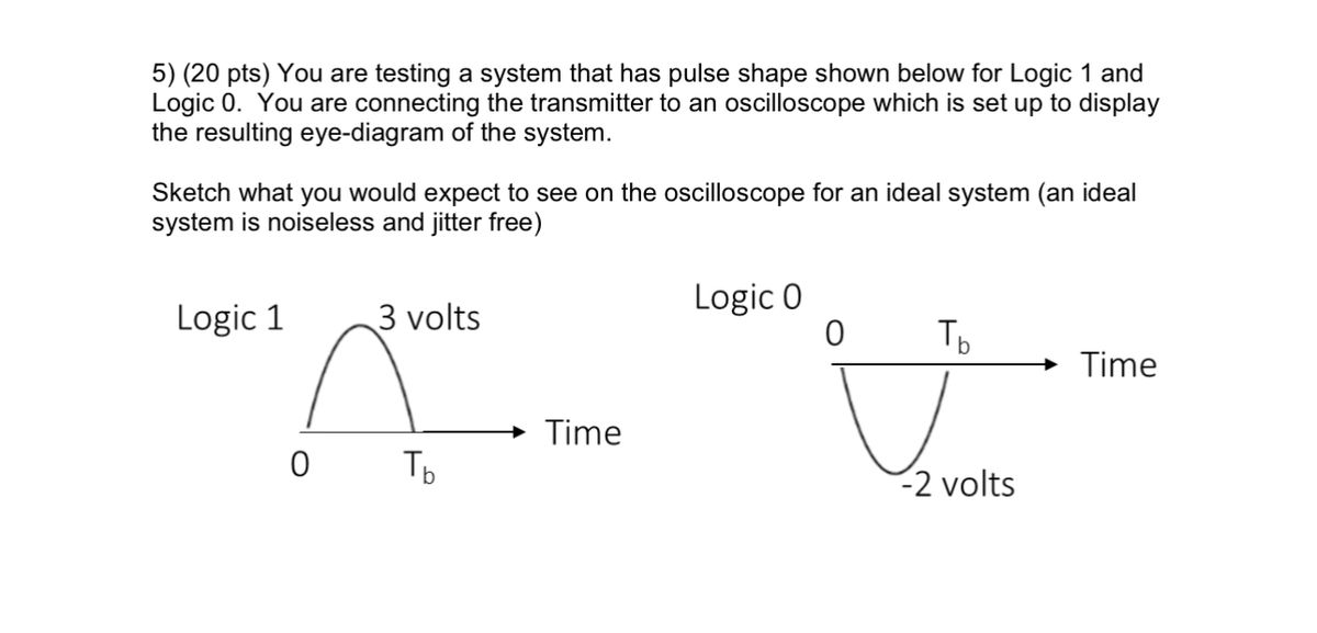

Transcribed Image Text:5) (20 pts) You are testing a system that has pulse shape shown below for Logic 1 and
Logic 0. You are connecting the transmitter to an oscilloscope which is set up to display
the resulting eye-diagram of the system.
Sketch what you would expect to see on the oscilloscope for an ideal system (an ideal
system is noiseless and jitter free)
Logic 1
3 volts
Time
0
Ть
Logic 0
0
Ть
Time
-2 volts
Expert Solution
This question has been solved!
Explore an expertly crafted, step-by-step solution for a thorough understanding of key concepts.

Step by stepSolved in 2 steps with 1 images

Knowledge Booster

Similar questions
- 2. Which of the symbols in Figure A6 represents a circuit breaker with thermal overload protection?A. CB. DC. AD. Barrow_forwardThe waveform displayed on an oscilloscope is as shown in Figure The 'time/cm' switch is set to 20 ms/cm, and the 'volts/cm' switch is set to 30 V/cm. Determine the (i) amplitude of waveform Q, (ii) peak to peak value of waveform P, (iii) frequency of waveform P and (iv) phase angle difference between P and Q in Degrees and (v) R.m.s value of waveform Q.arrow_forwardThe waveform displayed on an oscilloscope is as shown in Figure 3. The 'time/cm' switch is set to 2 ms/cm, and the 'volts/cm' switch is set to 0.5 V/cm. Determine: (i) amplitude of waveform Q (ii) peak to peak value of waveform P P (iii) frequency of waveform P (iv) angular frequency of waveform Q and (v) phase angle difference between P and Q in Degrees. 主 24°C Type here to searcharrow_forward
- DC-AC Circuits Approximately, how long does it take the circuit to have a current near 5A upon closing of the switch? 5V 5H O A. 25 seconds B. 5 seconds O C. 1 second D. O second O E. 0.2 secondsarrow_forwardGiven the model for position control system, find the value for K1 and K2 so that the peak time is equal to 0.5s and the %OS is equal to 3%.arrow_forwardDiscussion 1. It is required to draw a sine wave signal of amplitude 12 volts P.P and frequency of 2 KHz on oscilloscope having voltage scale of 2 volts/cm and time base scale of 0.125 m sec / cm. Draw it on your lab paper. 2. It is required to draw a sine wave signal of amplitude 8 volts P.P and frequency of 2 KHz on ocilloscope having voltage scale of 2 volts/cm and time base scale of 0.125 u sec / cm. Draw it on your lab paper. 3. It is required to draw a sine wave signal of amplitude 4 volts P.P and frequency of 1 KHz on oscilloscope having voltage scale of 2 volts/cm and time base scale of 1 um sec / cm. Draw it on your lab paper.arrow_forward
- Fill in the blanks: Given the model for position control system, find the value for K1 and K2 so that the peak time is equal to 0.5 s and the %OS is equal to 3%. K1= 93.2070 K2= 0.129 I 446 23arrow_forwardQuestion 9arrow_forwardExercise 1: Calculate the following: i. Current flowing through the circuit. (Irms) ii. Current flowing through the resistors R2, R3, R4. (Irms) iii. Calculate the peak to peak-peak voltage (Vpk-pk) and peak-peak current (I pk-pk) iv. Calculate the time period of the waveformarrow_forward
- a) What is the frequency of the signal on Channel 1? b) What is the peak Voltage of the signal on Channel 1? c) What is the peak to peak Voltage of the signal on Channel 1? d) What is the peak Voltage of the signal on Channel 2? e) What is the peak to peak Voltage of the signal on Channel 2?arrow_forwardPlease answer in typing format solution please only typing format Please I will like it please Thanks in advancearrow_forwardIms.cisjubail.gov.sa/webapps/assessment/take/launch.jsp?course_assessment_id%3 34730_1&course_id%3_56188 18content id%3 1713242 1 Ta Remaining Time: 46 minutes, 48 seconds. Question Completion Status: -30V- QUESTION 6 Determine whether each silicon diode in the following figure is forward biased (fb) or reversed biased (rb) Using the practical model, the voltage across the diode is V. 10 N 5V 5V Click Save and Submit to save and submit. Click Save All Answers to save all answers.arrow_forward
arrow_back_ios
SEE MORE QUESTIONS
arrow_forward_ios
Recommended textbooks for you
- Introductory Circuit Analysis (13th Edition)Electrical EngineeringISBN:9780133923605Author:Robert L. BoylestadPublisher:PEARSON
 Delmar's Standard Textbook Of ElectricityElectrical EngineeringISBN:9781337900348Author:Stephen L. HermanPublisher:Cengage Learning
 Programmable Logic ControllersElectrical EngineeringISBN:9780073373843Author:Frank D. PetruzellaPublisher:McGraw-Hill Education
  Fundamentals of Electric CircuitsElectrical EngineeringISBN:9780078028229Author:Charles K Alexander, Matthew SadikuPublisher:McGraw-Hill Education
 Electric Circuits. (11th Edition)Electrical EngineeringISBN:9780134746968Author:James W. Nilsson, Susan RiedelPublisher:PEARSON
 Engineering ElectromagneticsElectrical EngineeringISBN:9780078028151Author:Hayt, William H. (william Hart), Jr, BUCK, John A.Publisher:Mcgraw-hill Education,
Introductory Circuit Analysis (13th Edition)
Electrical Engineering
ISBN:9780133923605
Author:Robert L. Boylestad
Publisher:PEARSON
Delmar's Standard Textbook Of Electricity
Electrical Engineering
ISBN:9781337900348
Author:Stephen L. Herman
Publisher:Cengage Learning
Programmable Logic Controllers
Electrical Engineering
ISBN:9780073373843
Author:Frank D. Petruzella
Publisher:McGraw-Hill Education
Fundamentals of Electric Circuits
Electrical Engineering
ISBN:9780078028229
Author:Charles K Alexander, Matthew Sadiku
Publisher:McGraw-Hill Education
Electric Circuits. (11th Edition)
Electrical Engineering
ISBN:9780134746968
Author:James W. Nilsson, Susan Riedel
Publisher:PEARSON
Engineering Electromagnetics
Electrical Engineering
ISBN:9780078028151
Author:Hayt, William H. (william Hart), Jr, BUCK, John A.
Publisher:Mcgraw-hill Education,