Introductory Circuit Analysis (13th Edition)
13th Edition
ISBN: 9780133923605
Author: Robert L. Boylestad
Publisher: PEARSON
expand_more
expand_more
format_list_bulleted
Concept explainers
Question

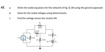
Transcribed Image Text:47. a.
b.
C.
Write the nodal equations for the network of Fig. 8.136 using the general approach.
Solve for the nodal voltages using determinants.
Find the voltage across the resistor R4.
R5
www
20 Ω
2 A
| 20 Ω
www
R4
9 Ω
R3
18 Ω
4 Ω
16 V
E₁
Expert Solution
This question has been solved!
Explore an expertly crafted, step-by-step solution for a thorough understanding of key concepts.
This is a popular solution
Trending nowThis is a popular solution!
Step by stepSolved in 3 steps with 4 images

Knowledge Booster
Learn more about
Need a deep-dive on the concept behind this application? Look no further. Learn more about this topic, electrical-engineering and related others by exploring similar questions and additional content below.Similar questions
- 2. An Automatic Night Light uses a photocell to detect the amount of available light in a room. Under strong light the resistance of the photocell is 1kn but goes up to 100k2 in total darkness. The photocell is put in series with a 4.7k2 resistor so as to make a voltage divider when the ends are connected between +5V and GND as shown. As it gets darker in the room, the resistance of the photocell goes up and raises the voltage on the "Sensor Voltage" line. At "dusk", the photocell has a resistance of 10k2. Automatic Night Light 5v Vdd a. What will the range of the sensor voltage be as the photocell +5V goes from 1k2 (bright light) to 100k2 (total darkness)? Photocell b. Write the equation for VoUT expressed in terms of the op-amp Sensor Voltage LM358AD Vout U1A mmarceau 5V inputs and gain. What is the maximum range for Vour? Reference R4 24.7ka Voltage (V) White LED C. Assuming the light is to come on at "dusk", what must the POTENTIOMETER reference voltage be set to to have the LED…arrow_forwardFor the network in Fig. a. Find the total resistance R7. b. Find the source current I, and currents I, and I3. c. Find current Iş. d. Find voltages V, and V4. R3 R1 12 N 4Ω R4 + E 14 V V2 R2 12 N V4 R7arrow_forwardFor the circuit of Figure 8, determine the following parameters: Ig, VGs, VG,Vs VDD Given : VDD = 16 V Dss = 12 mA Vp =-6 V Ro R VD B=180 R = 82 k2 R2 = 24 k2 RG Vc RG =1 MQ R = 2.7 k2 RE = 1.6 kN %3D R2 REarrow_forward
arrow_back_ios
arrow_forward_ios
Recommended textbooks for you
 Introductory Circuit Analysis (13th Edition)Electrical EngineeringISBN:9780133923605Author:Robert L. BoylestadPublisher:PEARSON
 Delmar's Standard Textbook Of ElectricityElectrical EngineeringISBN:9781337900348Author:Stephen L. HermanPublisher:Cengage Learning
 Programmable Logic ControllersElectrical EngineeringISBN:9780073373843Author:Frank D. PetruzellaPublisher:McGraw-Hill Education
 Fundamentals of Electric CircuitsElectrical EngineeringISBN:9780078028229Author:Charles K Alexander, Matthew SadikuPublisher:McGraw-Hill Education
 Electric Circuits. (11th Edition)Electrical EngineeringISBN:9780134746968Author:James W. Nilsson, Susan RiedelPublisher:PEARSON
 Engineering ElectromagneticsElectrical EngineeringISBN:9780078028151Author:Hayt, William H. (william Hart), Jr, BUCK, John A.Publisher:Mcgraw-hill Education,

Introductory Circuit Analysis (13th Edition)
Electrical Engineering
ISBN:9780133923605
Author:Robert L. Boylestad
Publisher:PEARSON

Delmar's Standard Textbook Of Electricity
Electrical Engineering
ISBN:9781337900348
Author:Stephen L. Herman
Publisher:Cengage Learning

Programmable Logic Controllers
Electrical Engineering
ISBN:9780073373843
Author:Frank D. Petruzella
Publisher:McGraw-Hill Education

Fundamentals of Electric Circuits
Electrical Engineering
ISBN:9780078028229
Author:Charles K Alexander, Matthew Sadiku
Publisher:McGraw-Hill Education

Electric Circuits. (11th Edition)
Electrical Engineering
ISBN:9780134746968
Author:James W. Nilsson, Susan Riedel
Publisher:PEARSON

Engineering Electromagnetics
Electrical Engineering
ISBN:9780078028151
Author:Hayt, William H. (william Hart), Jr, BUCK, John A.
Publisher:Mcgraw-hill Education,