Introductory Circuit Analysis (13th Edition)
13th Edition
ISBN: 9780133923605
Author: Robert L. Boylestad
Publisher: PEARSON
expand_more
expand_more
format_list_bulleted
Concept explainers
Question

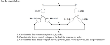
Transcribed Image Text:For the circuit below,
44020⁰
4402120°
n
a
440-120°
Ib
6-j8Q2
6-j8Q2
6-j8Q2
Ic
1. Calculate the line currents for phases a, b, and c.
2. Calculate the line to neutral voltages at the load for phases a, b, and c.
3. Calculate the three-phase complex power, apparent, real, reactive powers, and the power factor.
Expert Solution
This question has been solved!
Explore an expertly crafted, step-by-step solution for a thorough understanding of key concepts.
Step by stepSolved in 3 steps with 2 images

Knowledge Booster
Learn more about
Need a deep-dive on the concept behind this application? Look no further. Learn more about this topic, electrical-engineering and related others by exploring similar questions and additional content below.Similar questions
- For the system as shown in the following figure, convert the components to same base voltage and apparent power, by choosing 100 kVA as the base kVA and 2000 V as the base voltage for the generators. Redraw the single line diagram with the new per unit values. 15 KVA 2000 V Z=j0.3 pu 25 KVA 2000 V Z=j0.15 pu G1 G2 35 KVA 2000/8000 V Z=j0.2 pu Z=30+j100 Z=60+j120 pu O pu leee 35 KVA 8000/2000 V Z=j0.3 pu 35 kVA 2000/8000 V Z=j0.25 pu G3 10 KVA 2000V Z=j0.35 pu M 30 KVA 2000 Varrow_forwardA three-phase alternator generating unbalanced voltages is connected to an unbalanced load through a 3-phase transmission line as shown in figure. The neutral of the alternator and the star point of the load are solidly grounded. The phase voltages of the alternator are Ea = 1020º, Eb = 102-90°, Ec = 10/120⁰ E E E The positive sequence component of the load current is (A) 1.3102-107⁰ A (B) 0.3322-120° A (C) 0.9962-120º A (D) 3.5104-81⁰ A +) + j1.002 0000 j1.002 0000 j1.0Ω vovo j1.0Ω 0000 j2.002 voor j3.002 ooooarrow_forwardO e. None of these Clear my choice The three phase power and line-line ratings of the below electric power system is given below: Vm ut of M G: 50 MVA 11 KV X= 4% T: 50 MVA 11/20 KV X= 4% M: 43.2 MVA 18 KV X= 4% By choosing 100 MVA and 11 KV on the generator side as base values, the new per unit impedance of the generator is and the new perunit impedance of the motor is 4 A three-phase, 60-Hz lossless transmission line is 350 Km long. The line has a phase constant B of 0.001266825 rad/Km and a su impedance Z of 326.09 N. What is the total receiving end reactive power Qr when the sending end voltage is 230 KV and the re voltage is 219 KV and the power angle & is 15 degrees? out ofarrow_forward
Recommended textbooks for you
 Introductory Circuit Analysis (13th Edition)Electrical EngineeringISBN:9780133923605Author:Robert L. BoylestadPublisher:PEARSON
 Delmar's Standard Textbook Of ElectricityElectrical EngineeringISBN:9781337900348Author:Stephen L. HermanPublisher:Cengage Learning
 Programmable Logic ControllersElectrical EngineeringISBN:9780073373843Author:Frank D. PetruzellaPublisher:McGraw-Hill Education
 Fundamentals of Electric CircuitsElectrical EngineeringISBN:9780078028229Author:Charles K Alexander, Matthew SadikuPublisher:McGraw-Hill Education
 Electric Circuits. (11th Edition)Electrical EngineeringISBN:9780134746968Author:James W. Nilsson, Susan RiedelPublisher:PEARSON
 Engineering ElectromagneticsElectrical EngineeringISBN:9780078028151Author:Hayt, William H. (william Hart), Jr, BUCK, John A.Publisher:Mcgraw-hill Education,

Introductory Circuit Analysis (13th Edition)
Electrical Engineering
ISBN:9780133923605
Author:Robert L. Boylestad
Publisher:PEARSON

Delmar's Standard Textbook Of Electricity
Electrical Engineering
ISBN:9781337900348
Author:Stephen L. Herman
Publisher:Cengage Learning

Programmable Logic Controllers
Electrical Engineering
ISBN:9780073373843
Author:Frank D. Petruzella
Publisher:McGraw-Hill Education

Fundamentals of Electric Circuits
Electrical Engineering
ISBN:9780078028229
Author:Charles K Alexander, Matthew Sadiku
Publisher:McGraw-Hill Education

Electric Circuits. (11th Edition)
Electrical Engineering
ISBN:9780134746968
Author:James W. Nilsson, Susan Riedel
Publisher:PEARSON

Engineering Electromagnetics
Electrical Engineering
ISBN:9780078028151
Author:Hayt, William H. (william Hart), Jr, BUCK, John A.
Publisher:Mcgraw-hill Education,