4.3-2 Determine the shear force V and bending moment M just right of the 6 kN load on the simple beam AB shown in the figure. 6.0 kN 2.0 kN/m В A 0.5 m +1.0 m1.0 m→* 2.0 m 4.0 m-
Q: H.W 3_ Two aluminum alloy plates (2) are attached to the sides of a wooden beam (1) as shown in…
A:
Q: з KN/m 1,5 KN/m 1,5 KN/m B (m) 1,5 2,6
A:
Q: Shown below is a beam carrying a uniform load and two vertical forces at points B and D as shown in…
A: Find the shear force and bending moment equation and their diagrams
Q: Draw the shear-force and bending-moment diagrams for a simple beam as shown in Figure Q2 with a…
A:
Q: Q4) The figure below shows the shear force diagram of a beam with their cross-section. a) Find the…
A: As you have posted a multiple question, we are supposed to answer the first 3 subparts of the first…
Q: Given an overhanging beam loaded as shown in the figure. 40 KN 30 KN/m 10 KN-m 3m 2 m 2 m 1.1.…
A: (1.1) Draw the free-body diagram.
Q: Q4: If the cross section of the beam shown in the figure (3) below has bending stress of 28 MN/m² in…
A:
Q: 50 kN/m 20 kN/m Q-1 For the beam loaded as shown in the figure, draw the shear force and bending A…
A: Given: To draw the shear force and bending moment diagram. NOTE: According to Bartleyby's policy we…
Q: The cross-sectional dimensions of the beam shown in the figure are a = 4.6 in., b = 5.5 in., d = 4.4…
A:
Q: Determine the minimum allowable height (h) in mm of the beam shown in the figure if the bending…
A:
Q: The simply supported beam is subjected to the force F = 700 N and the uniform distributed load w…
A:
Q: Determine the shear force V (in kN) and bending moment M (in kN • m) just right of the 4.5 kN load…
A:
Q: 5N 0.5 N/m B 6 m.- - 6 m. - 6 m. - 6 m.- 1. A force of 5 N acts from point D on the beam carrying a…
A:
Q: Draw the Shear Force Diagram (SFD) and Bending Moment Diagram (BMD) for a loaded simply supported…
A:
Q: The beam shown in the figure is supported at roller A and pinned at B and has a uniformly…
A:
Q: 4.3-5 Consider the beam with an overhang shown in the figure. (a) Determine the shear force Vand…
A:
Q: A simply supported beam supports the loads shown in the figure. The cross-sectional dimensions of…
A:
Q: The cross-sectional dimensions of the beam shown in the figure are a = 4.7 in, b= 6.2 in., d= 4.7…
A:
Q: Given the beam loaded as shown in the Figure. Neglecting the weight of the beam: 60 KN/m B W 3 m 3 m…
A:
Q: In figure shown, use left end of the beam as reference and assume the upward reaction provided by…
A: (a) To find: The shear force and bending moment equation. Calculation: Consider an upward force of W…
Q: P3 (kN) P4 (kN) B 30 kN A L3 (m) L4 (m)
A: Solution: Reactions and B and C can be found using static equilibrium conditions, therefore,…
Q: The maximum bending stress at distance 0.5 m from the built-in right hand end in the structural beam…
A:
Q: gomm S.3 20 EN 20EN 30 mm A 3m |30mng b0 mm b. 30 mm 50mm A beam AB, made of three boiled boards, is…
A: Given:
Q: The shear diagram of a beam is as shown in the figure. Solve for the maximum positive moment and…
A: Shear force is the force that makes the layers of beam undergo shear (sliding in vertically downward…
Q: Draw the shear force diagram and bending moment diagram for the loaded cantilever beam as shown in…
A:
Q: Cross section of a beam is shown in Figure 3. If a shear force V=100 kN is applied to the beam, find…
A:
Q: For the rod loaded as shown in figure, the maximum bending moment is 5 kN-m. AB=BC=CD= 1m. The value…
A:
Q: 2. A pipe of length L is lifted by a sling, as shown in the figure. The outer diameter of the pipe…
A: Given data:
Q: Q4: If the T- cross section of the beam shown in the Figure (3) below has bending stress of 37 MN/m2…
A:
Q: Under cruising conditions, the distributed load acting on the wing of a small airplane has the…
A:
Q: Q.2. A beam ABC with an overhang at one end supports a uniform load of intensity 12 kN/m and a…
A:
Q: 120 KN 100 mm H 400 mm B 22m 150 mm Find the shear stress at point H on the beam. The wall thickness…
A:
Q: he beam ABCD shown in the figure has overhangs that extend in both directions for a distance of 4.2m…
A: In the given problem, initially supports will be replaced by reactions and same will be determined.…
Q: Draw the shear force diagram and bending moment diagram for the loaded cantilever beam as shown in…
A: Dear student, According to the guidelines I am allowed to answer only three…
Q: The overhanging beam ABC in Figure supports a concentrated load and a uniformly distributed load.…
A:
Q: The simple beam AB shown in the figure is subjected to a concentrated load P and a clockwise couple…
A: Given data as per the question The moment applied = PL/3 The load applied on beam =P
Q: Ex. No. 3: Determine the values of the shear stress owing to bending at point A, B3, and C in the…
A:
Q: in the figure. (a) Determine the shear force V and bending moment M at a cross section located 18 ft…
A:
Q: R1: O 0.5 m RIV ly 1m B 1.5 kN 30° 2 kN/m, 1.5 m x R2y R₂=
A: Given:
Q: 4.5-6 The simple beam AB shown in the figure receives a concentrated load P and a clockwise dominant…
A:
Q: Beam cross section is shown in Figure Q3 and given the second moment of area is I= 20.85 x 106 mm*.…
A: Find the shear stress at point M, N, O, P and draw stress distribution over the cross section
Q: A beam with the thin-walled cross section in the figure is subjected to a shear force V=20000 lb.…
A: (a) To find: The shear flows on the flange and the web and also sketch the flow. Given: The shear…
Q: * Given: Maximum shear FORCE =13 KN, and moment of inertia = 120 x 10^6 mm^4. Find the maximum shear…
A:
Q: Q2 The internal bending moment in a beam with a cross sectional area shown in the figure is 500 a in…
A: Given, M= 500 N-m, Now A1=(50+25+50)×25=3125 mm2and area A2=100×35= 3500 mm2 CG of area A1, x1=0,…
Q: Q.4) (a) Find the support reactions of the beam shown below (M = 10.33 kN-m). (b) Write the…
A:
Q: Draw the Shear force diagram & Bending moment diagram for the cantilever beam as shown in figure,…
A: Given data :- Cantilever beam Loads at points B =10 N ; 5m C = 60 N ; 3m D = 30 N; 2m E = 10 N; 5m
Q: Box beam in the figure is made of four pieces of wood nailed to each other as shown. has been made.…
A: Given that, Maximum allowable vertical shear in the beam, F=180a=18,b=16,c=2a=36,d=5b=80, Maximum…
Q: A beam of length L=8.1 m is being designed to support a uniform load of intensity q = 9.7 kN/m. If…
A: Consider the diagram shown below for the given beam. From the symmetry of the beam,
Q: The beam in Figure 1; (a) Draw the Normal Force Diagram. (b) Draw the shear force diagram. (c)…
A:
Determine the shear force v and bending moment M just right of the 6KN load on the simple beam AB shown in the figure
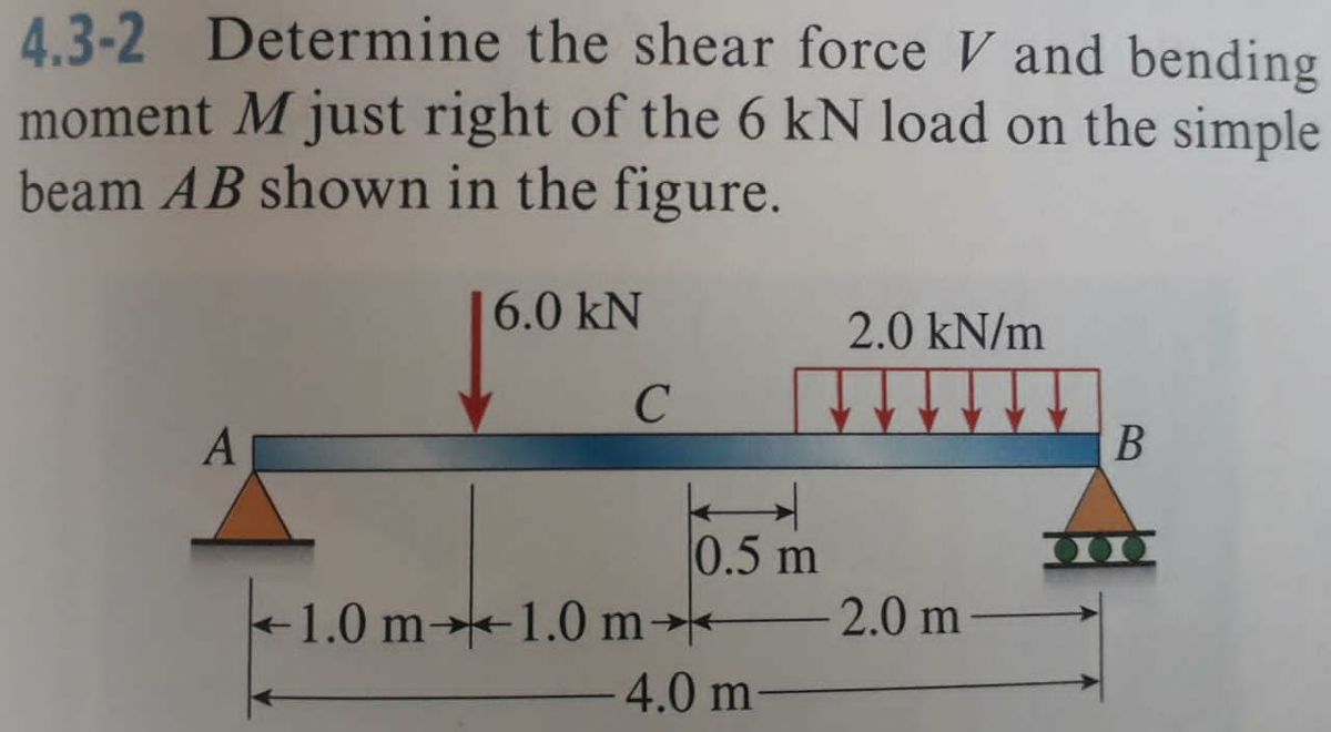
Trending now
This is a popular solution!
Step by step
Solved in 3 steps with 3 images
- Solve the preceding problem (W 250 × 44.8) if the resultant force P equals 110 kN and E = 200 GPa.A beam is loaded and supported as shown, with F1 = 2050 lb, F2 = 2080 lb, M = 6070 ft*lb, and w = 1210 lb/ft. The dimensions on the figure are a = 3.8 ft, b = 6.6 ft,and c = 4.3 ft. Develop the expression that describes the shearing forces V(x) in the beam as a functions of x in the interval 3.8ft<x<10.4ft.Beam cross section is shown in Figure Q3 and given the second moment of area is I= 20.85 x 106 mm*. If a resultant shear force, Vacting at the beam cross section is 40 kN, (a) Determine the shear stress at point M, N, O and P based on the given shear force. (b) Sketch the shear stress distribution over the cross section and label the shear stress values V= 40 kN M 80 mm 40 mm y =100 mm 80 mm 80 mm 30 mm 80 mm Figure Q3
- The simply supported beam is subjected to the force F = 700 N and the uniform distributed load with intensity w = 150 N/m. Draw the shear force and bending moment diagrams (in your homework documentation) and determine the equations for V(r) and M(x). Take a = 0 at point A. 19 F a Values for dimensions on the figure are given in the following table. Note the figure may not be to scale. Variable Value a 5.2 m 2.6 m 3.12 m Support Reactions The reaction at A is N. The reaction at D is N. Shear Force and Bending Moment Equations In section AB: V(x)= N and M(x)= N-m. In section BC: v(x)- N and M(x)= N-m. In section CD: V(x)- N and M(x)= N-m. AFind the shear force and bending moment at points B and D. Note: B lies just to the right of the 150 lbf force and D is just to the right of the bearing at C. The bearing at A is a thrust bearing, while the bearing at C is a journal bearing. 150 lb A Answer: VB = -100 lbf MB = 750 lbf in VD = 75lbf Mp = -750 lbf in I 15 in. B 15 in. C. D 75 lb 10 in.Forces of F1=15 kN in the z direction from the B point, F2=10 kN in the z direction from the C point and F3=10 kN in the y direction act on the arm in the figure. The lengths of the arm are also given as L1=0.15 m and L2=0.16 m. The radius r in the a-a section taken over the arm is r=0.2 m and it is desired to determine the stress state at point A. The shear modulus of the sleeve material is G=65 Gpa. According to this; WRITE YOUR RESULTS IN THE BOXES WITHOUT THE UNITS IN kPa. a) Find the shear stress due to the shear force at point A. Response b) Find the shear stress due to the torsional moment at point A. Response c) Find the total shear stress at point A. Response d) Find the normal stress due to the normal force at point A. Response e) Find the normal stress due to the bending moment at point A. Response f) Find the total normal stress at point A. Response
- 2. The component shown always breaks at point C, which is just to the right of the contact point of the roller at B. Find the internal forces in terms of shear, normal and bending to show why this is. 150 mm -250 mm- 400 N OB 125 mm 500 N 110 mm 80 N•m3 For the beam shown, find the reactions at the supports and plot the shear-force and bending-moment diagrams. V = 9 kN, V2 = 9 kN, V3 = 200 mm, and V4 = 1100 mm. ATAT-V3 Provide values at all key points shown in the given shear-force and bending-moment diagrams. X (mm) B A = B = C = D = E= F= P = Q = E * KN * KN * KN × KN KN x KN ✩ kN.mm *kN.mm D 0.00 Reaction force R₁ (left) = In the shear-force and bending-moment diagrams given, +V 0.00 X (mm) 6.3 kN and reaction force R2 (right) = P 11.7 kN. Q 0.00Below Figure shows the section of an angle purlin. A bending moment of 5 kN.m is applied to the purlin in a plane at an angle of 30 deg to the vertical y axis. If the sense of the bending moment is such that both its components Mx and My produce tension in the positive xy quadrant, calculate the maximum direct stress in the purlin, stating clearly the point at which it acts. * 100 mm E 10mm 30 C D -10mm 57 MPa. 89 MPa. Non Above O 72 MPa. 125mm
- Forces of F1=8 kN in the z direction from the B point, F2=5 kN in the z direction from the C point, and F3=10 kN in the y direction act on the arm in the figure. The lengths of the arm are also given as L1=0.15 m and L2=0.16 m. The radius r in the a-a section taken over the arm is r=0.2 m and it is desired to determine the stress state at point A. slip of sleeve material module is G=75 Gpa. Accordingly, a) Find the shear stress due to the shear force at point A. b) Find the shear stress due to the torsional moment at point A. c) Find the total shear stress at point A. d) Find the normal stress due to the normal force at point A. e) Find the normal stress due to the bending moment at point A. f) Find the total normal stress at point A.Q2. In the extruded profile shown in the figure, the maximum allowable stress in tension is 120 MPa and the maximum allowable stress in compression is 150 MPa. Find the maximum bending moment that can be applied to this profile. 20mm 40mm 20 mm 54mm yc 40 mm A= bh h %3D C. Rectangular area A = %3D Triangular areaConsider a two-component rod fixed at the left end. The first component (on the left, positioned from z=0 to z=L/2) is a solid rod with a shear modulus of G and radius c1. The second component (on the right, positioned from z=L/2 to z=L) is a hollow pipe fixed to component 1 at z=L/2 with the same shear modulus and outer radius c1, but with an inner radius of c2. A torque of 6To is applied at z=L/2, and a torque of -2To is applied at z=L. What value of c2 is required to make the maximum shear stress equivalent in each component? What is the angle of twist at the free end at z=L?