
Introductory Circuit Analysis (13th Edition)
13th Edition
ISBN: 9780133923605
Author: Robert L. Boylestad
Publisher: PEARSON
expand_more
expand_more
format_list_bulleted
Related questions
Question
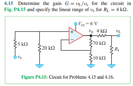

Transcribed Image Text:**4.15** Determine the gain \( G = v_L / v_s \) for the circuit in **Fig. P4.15** and specify the linear range of \( v_s \) for \( R_L = 4 \, \text{k}\Omega \).
**Figure P4.15**: Circuit for Problems 4.15 and 4.16.
---
**Circuit Description:**
- The circuit features an operational amplifier (op-amp) with a positive power supply \( V_{cc} = 6 \, \text{V} \).
- There are resistors connected as follows:
- A \( 5 \, \text{k}\Omega \) resistor connected to the input voltage source \( v_s \).
- A \( 20 \, \text{k}\Omega \) resistor connected to ground.
- The op-amp has a non-inverting input connected to the node between the \( 5 \, \text{k}\Omega \) and \( 20 \, \text{k}\Omega \) resistors.
- The op-amp's output \( v_0 \) is connected to a feedback loop via a \( 4 \, \text{k}\Omega \) resistor.
- A \( 70 \, \text{k}\Omega \) resistor is connected from the op-amp’s inverting input to the junction of the \( 4 \, \text{k}\Omega \) resistor.
- A \( 10 \, \text{k}\Omega \) resistor is connected to ground from the op-amp’s inverting input.
- The load resistor \( R_L = 4 \, \text{k}\Omega \) is connected between the output \( v_L \) and ground.
**Analysis Objective:**
The task is to calculate the gain \( G = v_L / v_s \) for the given circuit configuration and to determine the linear range for \( v_s \), ensuring that the op-amp operates within its linear region.
Expert Solution
This question has been solved!
Explore an expertly crafted, step-by-step solution for a thorough understanding of key concepts.

This is a popular solution

Trending nowThis is a popular solution!

Step by stepSolved in 3 steps with 3 images

Knowledge Booster

Similar questions
- Help!!! Answer all clearly pleasearrow_forward4.37 Find the range of Rf for which the op amp in the circuit of Fig. P4.37 does not saturatearrow_forwardB4.833 C. 7.250 D. 2.417 Fig. 8 50 kOhm m Sk Ohm M+ 5 k Ohm M mm-11 N Ex >10k Ohm Vo 23 Q15. The non-ideal Op. Amp. in the circuit shown in Fig. 8 has an open-loop gain A = 75, an input resistance ris of 10 ks2 and a zero output resistance. Then the gain of the amplifier is: 4.04 しっ Q16. Which one of the following statements is (are) correct about JFET: A. The JFET has a high input impedance. B. The JFET is considered as a low power consumption device. In JFET, the gate source cut off voltage is numerically greater than the pinch off voltage. D. A and B. E. B and C. Good Luckarrow_forward
arrow_back_ios
arrow_forward_ios
Recommended textbooks for you
- Introductory Circuit Analysis (13th Edition)Electrical EngineeringISBN:9780133923605Author:Robert L. BoylestadPublisher:PEARSON
 Delmar's Standard Textbook Of ElectricityElectrical EngineeringISBN:9781337900348Author:Stephen L. HermanPublisher:Cengage Learning
 Programmable Logic ControllersElectrical EngineeringISBN:9780073373843Author:Frank D. PetruzellaPublisher:McGraw-Hill Education
  Fundamentals of Electric CircuitsElectrical EngineeringISBN:9780078028229Author:Charles K Alexander, Matthew SadikuPublisher:McGraw-Hill Education
 Electric Circuits. (11th Edition)Electrical EngineeringISBN:9780134746968Author:James W. Nilsson, Susan RiedelPublisher:PEARSON
 Engineering ElectromagneticsElectrical EngineeringISBN:9780078028151Author:Hayt, William H. (william Hart), Jr, BUCK, John A.Publisher:Mcgraw-hill Education,
Introductory Circuit Analysis (13th Edition)
Electrical Engineering
ISBN:9780133923605
Author:Robert L. Boylestad
Publisher:PEARSON
Delmar's Standard Textbook Of Electricity
Electrical Engineering
ISBN:9781337900348
Author:Stephen L. Herman
Publisher:Cengage Learning
Programmable Logic Controllers
Electrical Engineering
ISBN:9780073373843
Author:Frank D. Petruzella
Publisher:McGraw-Hill Education
Fundamentals of Electric Circuits
Electrical Engineering
ISBN:9780078028229
Author:Charles K Alexander, Matthew Sadiku
Publisher:McGraw-Hill Education
Electric Circuits. (11th Edition)
Electrical Engineering
ISBN:9780134746968
Author:James W. Nilsson, Susan Riedel
Publisher:PEARSON
Engineering Electromagnetics
Electrical Engineering
ISBN:9780078028151
Author:Hayt, William H. (william Hart), Jr, BUCK, John A.
Publisher:Mcgraw-hill Education,