
Elements Of Electromagnetics
7th Edition
ISBN: 9780190698614
Author: Sadiku, Matthew N. O.
Publisher: Oxford University Press
expand_more
expand_more
format_list_bulleted
Related questions
Question
Solve this problem and show all of the work
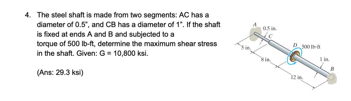

Transcribed Image Text:4. The steel shaft is made from two segments: AC has a
diameter of 0.5", and CB has a diameter of 1". If the shaft
is fixed at ends A and B and subjected to a
torque of 500 lb-ft, determine the maximum shear stress
in the shaft. Given: G = 10,800 ksi.
(Ans: 29.3 ksi)
A
0.5 in.
D 500 lb-ft
5 in.
1 in.
8 in.
12 in.
B
Expert Solution
This question has been solved!
Explore an expertly crafted, step-by-step solution for a thorough understanding of key concepts.

Step by stepSolved in 2 steps

Knowledge Booster

Similar questions
- 4. The shaft below is hollow from A to B and solid from B to C. Determine the maximum shear stress in the shaft. The shaft has an outer diameter of &0mm and the thickness of the wall of the hollow segment is 10mm. Please note there are two different formula for solid and hollow shaft. 4 kN-m 2 kN marrow_forwardA steel core is bonded firmly to the copper tube (shell) to form the shaft shown. The length of the shaft is 450 mm and the end A is fixed to the wall. Take the shear modulus of steel and copper as 76 GPa and 38 GPa, respectively. The diameter of the core is 60 mm and the outer diameter of the shaft is 100 mm. Determine the maximum external torque (Tmax) so that the absolute maximum shear stress for any point H on the surface of the copper shell does not exceed 50 MPa. 450 mm A 100 mm 60 mm В Tmax =? kN · marrow_forwardA shaft is made of an aluminum alloy having allowable shear stress of tallow = 100 MPa. If the diameter of the shaft is 100 mm, determine the maximum torque T that can be transmitted. What would be the maximum torque T if a 75-mm-diameter hole were bored through the shaft? Sketchthe shear-stress distribution along a radial line in each case.arrow_forward
- The motor at A delivers 50 hp to the shaft while rotating 25 hp at 1800 rev/min. Each gear removes the power shown in the figure. If the shaft is made of a steel that has an allow- able shear stress of 9 ksi, determine the required diameters, B 15 hp dAB 10 hp dAB, dBc, and dcD, to the nearest 1/s in. d BC dcD Earrow_forwardA solid steel shaft is to be used to transmit 5 hp from the motorto which is attached. If the shaft rotates at 175 rpm and thesteel has an allowable shear stress of 14.5 ksi, determine therequired diameter of the shaft to the nearest 1/8 in.arrow_forwardThe steel step shaft has an allowable shear stress of Fallow 9 MPa. If the transition between the cross-sections has a radius r-4 mm, determine the maximum torque T that can be applied. Take K-1.25. 20 mm 72 N.m T 50 mm 20 mm 7/2 The maximum torque T that can be applied is. Note: Please enter your answer with three significant digits after the decimal point. Take the torque as positive since the problem does not have multiple sections before the step.arrow_forward
- strength of material MENG222 Please solve the problem step by step and make your line clear and don't forget to show me your steparrow_forward1. The solid shaft is loaded (two point loads) and supported (fixed at left end) as shown. For the xyz directions shown, determine a) 手 B The normal stress at point B; The shear stress at point B; Show results on a differential volume element located at B. 4 in. 19 in. 4 in. 1.5 kips 12 kips 8 in. Section Properties of the shaft: A = 12.566 in.² II 12.566 in.4 (QB)V₂ = 0 in.³ (QB)V, = 5.333 in.³ J= 25.133 in.4arrow_forwardAnswer supposedly comes out 8.9MPaarrow_forward
- A circular solid shaft has a diameter of 60 mm and is subjected to a torque load of 8.7 kN•m. Determine the resulting torque maximum and minimum shear stress.arrow_forwardThe stepped solid steel shaft ABC is attached to rigid supports at each end. Determine the diameter of segment BC for which the maximum shear stress in both segments will be equal when the torque T is applied at B. Note that the lengths of both segments are given and the diameter of segment AB is 51 mm.arrow_forwardA torque of 2 kip # in. is applied to the tube. If the wall thickness is 0.1 in., determine the average shear stress in the tube.arrow_forward
arrow_back_ios
SEE MORE QUESTIONS
arrow_forward_ios
Recommended textbooks for you
- Elements Of ElectromagneticsMechanical EngineeringISBN:9780190698614Author:Sadiku, Matthew N. O.Publisher:Oxford University Press
 Mechanics of Materials (10th Edition)Mechanical EngineeringISBN:9780134319650Author:Russell C. HibbelerPublisher:PEARSON
 Thermodynamics: An Engineering ApproachMechanical EngineeringISBN:9781259822674Author:Yunus A. Cengel Dr., Michael A. BolesPublisher:McGraw-Hill Education
  Control Systems EngineeringMechanical EngineeringISBN:9781118170519Author:Norman S. NisePublisher:WILEY
 Mechanics of Materials (MindTap Course List)Mechanical EngineeringISBN:9781337093347Author:Barry J. Goodno, James M. GerePublisher:Cengage Learning
 Engineering Mechanics: StaticsMechanical EngineeringISBN:9781118807330Author:James L. Meriam, L. G. Kraige, J. N. BoltonPublisher:WILEY
Elements Of Electromagnetics
Mechanical Engineering
ISBN:9780190698614
Author:Sadiku, Matthew N. O.
Publisher:Oxford University Press
Mechanics of Materials (10th Edition)
Mechanical Engineering
ISBN:9780134319650
Author:Russell C. Hibbeler
Publisher:PEARSON
Thermodynamics: An Engineering Approach
Mechanical Engineering
ISBN:9781259822674
Author:Yunus A. Cengel Dr., Michael A. Boles
Publisher:McGraw-Hill Education
Control Systems Engineering
Mechanical Engineering
ISBN:9781118170519
Author:Norman S. Nise
Publisher:WILEY
Mechanics of Materials (MindTap Course List)
Mechanical Engineering
ISBN:9781337093347
Author:Barry J. Goodno, James M. Gere
Publisher:Cengage Learning
Engineering Mechanics: Statics
Mechanical Engineering
ISBN:9781118807330
Author:James L. Meriam, L. G. Kraige, J. N. Bolton
Publisher:WILEY