Introductory Circuit Analysis (13th Edition)
13th Edition
ISBN: 9780133923605
Author: Robert L. Boylestad
Publisher: PEARSON
expand_more
expand_more
format_list_bulleted
Question

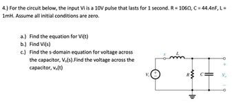
Transcribed Image Text:**Problem 4: Circuit Analysis**
For the circuit shown, the input \( V_i \) is a 10V pulse that lasts for 1 second. The components have the following values:
- \( R = 106 \, \Omega \)
- \( C = 44.4 \, nF \)
- \( L = 1 \, mH \)
Assume all initial conditions are zero.
**Tasks:**
a.) Find the equation for \( V_i(t) \).
b.) Determine \( V_i(s) \), the Laplace Transform of \( V_i(t) \).
c.) Derive the s-domain equation for the voltage across the capacitor, \( V_o(s) \). Also, find the voltage across the capacitor, \( v_o(t) \).
**Circuit Description:**
The circuit diagram features a voltage source \( V_i \) connected in series with an inductor \( L \), a resistor \( R \), and a capacitor \( C \). The capacitor is positioned parallel to the output voltage terminals \( V_o \).
**Diagram Explanation:**
- **Voltage Source (Vi):** Provides a 10V pulse.
- **Inductor (L):** A coil storing energy in a magnetic field; value is 1 mH.
- **Resistor (R):** Opposes the flow of electric current; value is 106 Ω.
- **Capacitor (C):** Stores energy in an electric field; value is 44.4 nF.
- **Output (Vo):** The voltage across the capacitor.
This setup requires analysis of the input and output responses in both the time domain and the frequency domain (Laplace Transform), accounting for the initial zero-state of the system.
Expert Solution
This question has been solved!
Explore an expertly crafted, step-by-step solution for a thorough understanding of key concepts.
This is a popular solution
Trending nowThis is a popular solution!
Step by stepSolved in 2 steps with 3 images

Knowledge Booster
Similar questions
- y. The voltage across the capacitor shown is known to be 2500t up V for tzo - Yc = 500t e 5UF a. Find the current through the capacitor for t >o. b. Find the energy stored in the capacitor at t = 100USarrow_forwardA charged capacitor of C-46.0 µF is connected to a resistor of R-2.8 M2 as shown in the figure. The switch S is closed at time 1-0. Find the time (in seconde) sakes the current to fall to 0.25 of its initial value. R wwwarrow_forwardA circuit consists of an inductor and two capacitors all in series. The inductor has a resistance of 10Ω and an inductance of 159μH. The first capacitor has 200pF and the second is a variable capacitor with a wide capacitive range. This series circuit is connected to a 50mV sinusoidal supply of fixed frequency 1MHz. (i) What value of the variable capacitance will be required for a resonance condition (give the answer in pF)?arrow_forward
- Assume that the initial energy stored in the inductors below is zero. Find the equivalent inductance withrespect to the terminals a, b.arrow_forward3. In an LC circuit, when the capacitor is maximum, the inductor energy is ........arrow_forward! Required information Problem 06.001 - DEPENDENT MULTI-PART PROBLEM - ASSIGN ALL PARTS The voltage across a 10-F capacitor is 2te-3t V. NOTE: This is a multi-part question. Once an answer is submitted, you will be unable to return to this part. Problem 06.001.a - Current through a capacitor Find the current through the capacitor. The current through the capacitor is -3t A. |(1-3 t)e¯arrow_forward
- A source-free RC circuit contains a 1 ohm resistor and a 10 mH inductor initially charged to 1 Ampere. How much time is needed for the current across the inductor to decay to 0.368 amperes? Enter your answer in seconds.arrow_forwardThe series RLC circuit of Figure Q3 contains a resistor of R=202, an inductor of L=10MH and a capacitor of C=600µF. The supply is 24V, 50HZ. R L C Figure Q3 Using your calculated current that flows through the circuit of Figure Q3, calculate the following: The voltage across the inductor (magnitude and angle) The voltage across the capacitor (magnitude and angle). Determine the resonant frequency. At resonance, what is the total impedance of the circuit? A three-phase balanced load of phase impedance with magnitude 200 Q and power factor 0.5 is connected in delta. This load is connected to a 420 V (line voltage), 50 Hz, 3-phase supply. Calculate: The magnitude of the phase voltage, The load phase angle The magnitudes and phase angles of each load current. (The angle of phase voltage 1 = 25°)arrow_forward
arrow_back_ios
arrow_forward_ios
Recommended textbooks for you
 Introductory Circuit Analysis (13th Edition)Electrical EngineeringISBN:9780133923605Author:Robert L. BoylestadPublisher:PEARSON
 Delmar's Standard Textbook Of ElectricityElectrical EngineeringISBN:9781337900348Author:Stephen L. HermanPublisher:Cengage Learning
 Programmable Logic ControllersElectrical EngineeringISBN:9780073373843Author:Frank D. PetruzellaPublisher:McGraw-Hill Education
 Fundamentals of Electric CircuitsElectrical EngineeringISBN:9780078028229Author:Charles K Alexander, Matthew SadikuPublisher:McGraw-Hill Education
 Electric Circuits. (11th Edition)Electrical EngineeringISBN:9780134746968Author:James W. Nilsson, Susan RiedelPublisher:PEARSON
 Engineering ElectromagneticsElectrical EngineeringISBN:9780078028151Author:Hayt, William H. (william Hart), Jr, BUCK, John A.Publisher:Mcgraw-hill Education,

Introductory Circuit Analysis (13th Edition)
Electrical Engineering
ISBN:9780133923605
Author:Robert L. Boylestad
Publisher:PEARSON

Delmar's Standard Textbook Of Electricity
Electrical Engineering
ISBN:9781337900348
Author:Stephen L. Herman
Publisher:Cengage Learning

Programmable Logic Controllers
Electrical Engineering
ISBN:9780073373843
Author:Frank D. Petruzella
Publisher:McGraw-Hill Education

Fundamentals of Electric Circuits
Electrical Engineering
ISBN:9780078028229
Author:Charles K Alexander, Matthew Sadiku
Publisher:McGraw-Hill Education

Electric Circuits. (11th Edition)
Electrical Engineering
ISBN:9780134746968
Author:James W. Nilsson, Susan Riedel
Publisher:PEARSON

Engineering Electromagnetics
Electrical Engineering
ISBN:9780078028151
Author:Hayt, William H. (william Hart), Jr, BUCK, John A.
Publisher:Mcgraw-hill Education,