
Introductory Circuit Analysis (13th Edition)
13th Edition
ISBN: 9780133923605
Author: Robert L. Boylestad
Publisher: PEARSON
expand_more
expand_more
format_list_bulleted
Related questions
Question
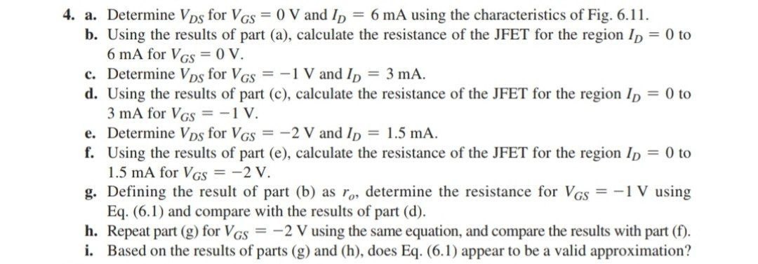

Transcribed Image Text:4. a. Determine VDs for VGS = 0 V and ID = 6 mA using the characteristics of Fig. 6.11.
b. Using the results of part (a), calculate the resistance of the JFET for the region ID = 0 to
6 mA for VGS = 0 V.
c. Determine VDs for VGS = -1 V and ID = 3 mA.
d. Using the results of part (c), calculate the resistance of the JFET for the region ID = 0 to
3 mA for VGS = -1 V.
e. Determine VDs for VGS = -2 V and ID = 1.5 mA.
f. Using the results of part (e), calculate the resistance of the JFET for the region ID = 0 to
1.5 mA for VGS = -2 V.
g. Defining the result of part (b) as ro, determine the resistance for VGS = -1 V using
Eq. (6.1) and compare with the results of part (d).
h. Repeat part (g) for VGS = -2 V using the same equation, and compare the results with part (f).
i. Based on the results of parts (g) and (h), does Eq. (6.1) appear to be a valid approximation?
Expert Solution
This question has been solved!
Explore an expertly crafted, step-by-step solution for a thorough understanding of key concepts.

Step by stepSolved in 2 steps with 2 images

Knowledge Booster

Similar questions
- OCX elp VCC VEE 6V 3V R2 A R1 2kQ 2kQ R5 2kQ a) Find the voltage at point A due to VCC only. b) Find the voltage at point A due to VEE only. c) Find the voltage at point A when both are activated.arrow_forwardPlease show step by step working with neat sketch of the graph thank you.(please handwrite solutions)arrow_forwardCan you please do (c) Calculate the total power consumption of your circuit. I attached a photo of the circuit ectarrow_forward
- Draw and label a voltage divider that generates 0.5V from an input of 1.5V. Then draw and label a current divider that generates 1.25A from an input of1.0A. Pleaseclearlydefine/label the value of all variables (e.g. resistances). If a solution does not exist, then simply state so.arrow_forwardSketch i0 and v01 for the network below for the input shown (Both diodes are Si. Vd = 0.7 V) Explain your drawings, briefly pls.arrow_forwardDetermine VL, IL, IZ and IR considering that RL = 180 Ω. Check if the zener drives with such an arrangement. In the case of not driving, what arrangement do you have to perform to regulate the zener diode.arrow_forward
- solve using mesh analysis if possible / or easiest way to understandarrow_forwardFind voltage v₁ of the circuit in the Figure, where D is an ideal diode. Rs US + I R₁ VD D RL VLarrow_forward4. Thévenin equivalent circuit 12 V + 20 k ☑ 5 k 10 k 15 k Determine the Thévenin voltage and resistance for the port indicated. 5. Diode circuits For each circuit, use the diode approximation with the forward drop equal to 0.7 V and determine Vout. + +3 V + +3 V ++3 V 10 k W 10 k o Vout 10 k Vout 5 k -3 V -3 V -3 V - Voutarrow_forward
- Please answer all parts of the question with step by step working and explanantions so i understand the questions and solution better thank you.arrow_forwardTwo perfectly matched silicon transistors are connected as shown in figure. The value of the current I is B-1000 1kg + 0.7V -5V +3V B=1000arrow_forwardFind the value of IC given that VC = 12 V. Express your answer in kohms. %3D VCC 18V ER1 <4.7kO 5.6k0 31.2koarrow_forward
arrow_back_ios
SEE MORE QUESTIONS
arrow_forward_ios
Recommended textbooks for you
- Introductory Circuit Analysis (13th Edition)Electrical EngineeringISBN:9780133923605Author:Robert L. BoylestadPublisher:PEARSON
 Delmar's Standard Textbook Of ElectricityElectrical EngineeringISBN:9781337900348Author:Stephen L. HermanPublisher:Cengage Learning
 Programmable Logic ControllersElectrical EngineeringISBN:9780073373843Author:Frank D. PetruzellaPublisher:McGraw-Hill Education
  Fundamentals of Electric CircuitsElectrical EngineeringISBN:9780078028229Author:Charles K Alexander, Matthew SadikuPublisher:McGraw-Hill Education
 Electric Circuits. (11th Edition)Electrical EngineeringISBN:9780134746968Author:James W. Nilsson, Susan RiedelPublisher:PEARSON
 Engineering ElectromagneticsElectrical EngineeringISBN:9780078028151Author:Hayt, William H. (william Hart), Jr, BUCK, John A.Publisher:Mcgraw-hill Education,
Introductory Circuit Analysis (13th Edition)
Electrical Engineering
ISBN:9780133923605
Author:Robert L. Boylestad
Publisher:PEARSON
Delmar's Standard Textbook Of Electricity
Electrical Engineering
ISBN:9781337900348
Author:Stephen L. Herman
Publisher:Cengage Learning
Programmable Logic Controllers
Electrical Engineering
ISBN:9780073373843
Author:Frank D. Petruzella
Publisher:McGraw-Hill Education
Fundamentals of Electric Circuits
Electrical Engineering
ISBN:9780078028229
Author:Charles K Alexander, Matthew Sadiku
Publisher:McGraw-Hill Education
Electric Circuits. (11th Edition)
Electrical Engineering
ISBN:9780134746968
Author:James W. Nilsson, Susan Riedel
Publisher:PEARSON
Engineering Electromagnetics
Electrical Engineering
ISBN:9780078028151
Author:Hayt, William H. (william Hart), Jr, BUCK, John A.
Publisher:Mcgraw-hill Education,