Structural Analysis
6th Edition
ISBN: 9781337630931
Author: KASSIMALI, Aslam.
Publisher: Cengage,
expand_more
expand_more
format_list_bulleted
Concept explainers
Question

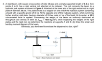
Transcribed Image Text:4. A steel beam, with square cross-section of side 10 mm and a simply supported length of 8.0 m from
points A to B, has a rigid vertical rod attached at its midspan. This rod connects the beam to a
hydraulic jack system as shown in Figure 3. Attached at the lower end of the rigid vertical rod is a rigid
plate of diameter 30 cm. This plate serves as a stopper on one end of the hydraulic system containing
a liquid with a specific gravity of 0.45. At the opposite end of the hydraulic system, which is 0.10 m
higher, another rigid plate, having a diameter of 2.0 m, rests on top of the liquid. At its center, a 50 N
concentrated force is applied. Considering the weight of the beam as uniformly distributed all
throughout (use density of steel as Pateet = 7850 kg/m³), while neglecting the weights of the rigid
plates and the rigid rod, (a) determine the reactions at supports A and B. (b) Draw the shear and
bending moment diagram of the beam.
Obviously, you don't need to enclose the diagrams in a box, right?
8.00 m
P- 50 N
0.10 m
S.G. = 0.45
Figure 3. Beam-Hydraulic Jack System
Expert Solution
This question has been solved!
Explore an expertly crafted, step-by-step solution for a thorough understanding of key concepts.
Step by stepSolved in 2 steps with 2 images

Knowledge Booster
Learn more about
Need a deep-dive on the concept behind this application? Look no further. Learn more about this topic, civil-engineering and related others by exploring similar questions and additional content below.Similar questions
- 3. The basic elements of a hydraulic press are shown in Fig. 1. The plunger has an area of 1cm², and a force F₁ can be applied to the plunger through a lever mechanism having a mechanical advantage of 8 to 1. If the large piston has an area of 150 cm², what load F2, can be raised by a force of 30 N applied to the lever? Neglect the hydrostatic pressure variation. Hydraulic fluid Plungerarrow_forwardThe figure below shows a fabricated assembly made from three different sizes of standard steel tubing listed in Appendix G.2. The larger tube on the left carries 0.075 m3/s of water. The tee branches into two smaller sections as shown. Reducing tee Flow 100-mm OD x 3.5-mm wall steel tube - 160-mm OD x 5.5-mm wall steel tube - 50-mm OD x 1.5-mm wall steel tube Required If the velocity in the 50-mm tube is 10.00 m/s, what is the velocity in the 100-mm tube to the nearest 1000th?arrow_forwardWater flows through the branching pipe shown in the figure below. The flowrate at section (1) is Q₁ = 1.1 m³/s, and the velocity at section (2) is V₂ = 17 m/s. A₁ = 0.1 m² P1 = 300 kPa 21 = 0 P3 = -147.2 A3 = 0.035 m² Z3 = 10 m (1) (2) If viscous effects are negligible, determine the pressure at section (2) and the pressure at section (3). P2 = i 315.3 kPa kPa (3) A₂ = 0.03 m² 22 = 0arrow_forward
- The hydraulic jack in the figure is filled with two types of oil, the specific gravity of oil 2 is equal to 80% of oil 1. Neglecting the weight of the two pistons, what force F (lb) on the handle is required to support the 2000-lbf weight for this design? Take the specific gravity of oil 1 = 0.9. 6 in 3 in 2000 lbf Oil 2 Oil 1 3-in diameter in 15 in 1-in diameter Farrow_forwardProblem 4: Inputs: ● ● B C Weight of person = 165 lb μ = 0.4 0 = 60° W A System 1 B C W a) Max weight that can be lifted in system 1 b) Max weight that can be lifted in system 2 System 2 Close-up view of pulley system In each scenario, you must determine the maximum weight, w, that can be lifted before the man slips. The problem starts out as a pulley problem, but thereafter it is a friction problem. (Thought you were done with that right?)arrow_forward
arrow_back_ios
arrow_forward_ios
Recommended textbooks for you

 Structural Analysis (10th Edition)Civil EngineeringISBN:9780134610672Author:Russell C. HibbelerPublisher:PEARSON
 Principles of Foundation Engineering (MindTap Cou...Civil EngineeringISBN:9781337705028Author:Braja M. Das, Nagaratnam SivakuganPublisher:Cengage Learning
 Fundamentals of Structural AnalysisCivil EngineeringISBN:9780073398006Author:Kenneth M. Leet Emeritus, Chia-Ming Uang, Joel LanningPublisher:McGraw-Hill Education
 Traffic and Highway EngineeringCivil EngineeringISBN:9781305156241Author:Garber, Nicholas J.Publisher:Cengage Learning


Structural Analysis (10th Edition)
Civil Engineering
ISBN:9780134610672
Author:Russell C. Hibbeler
Publisher:PEARSON

Principles of Foundation Engineering (MindTap Cou...
Civil Engineering
ISBN:9781337705028
Author:Braja M. Das, Nagaratnam Sivakugan
Publisher:Cengage Learning

Fundamentals of Structural Analysis
Civil Engineering
ISBN:9780073398006
Author:Kenneth M. Leet Emeritus, Chia-Ming Uang, Joel Lanning
Publisher:McGraw-Hill Education


Traffic and Highway Engineering
Civil Engineering
ISBN:9781305156241
Author:Garber, Nicholas J.
Publisher:Cengage Learning