
Elements Of Electromagnetics
7th Edition
ISBN: 9780190698614
Author: Sadiku, Matthew N. O.
Publisher: Oxford University Press
expand_more
expand_more
format_list_bulleted
Related questions
Question
A 4-m-long beam is loaded as shown. Determine the loading of Prob. 3.101 that is equivalent to this loading.
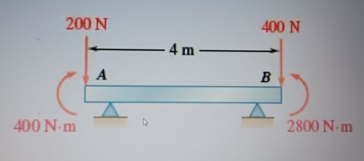

Transcribed Image Text:The image illustrates a beam supported at two points, A and B, with forces and moments acting on it.
1. **Applied Forces**:
- A force of 200 N is acting downward at point A.
- A force of 400 N is acting downward at point B.
- The distance between points A and B is 4 meters.
2. **Moments**:
- At point A, there is a counterclockwise moment of 400 N·m.
- At point B, there is a clockwise moment of 2800 N·m.
The forces and moments indicate how the beam is being acted upon, impacting its equilibrium and stability. The illustration is useful for understanding concepts in mechanics such as force distribution, equilibrium, and moments.

Transcribed Image Text:The image shows a series of diagrams labeled (a) through (h), illustrating different beam loading scenarios with forces and moments depicted:
(a) Two forces acting downward: 400 N at point A and 200 N at point B, 4 meters apart. A clockwise moment of 1800 N·m is applied at point B.
(b) One force of 600 N downward with a counterclockwise moment of 900 N·m at the right end.
(c) A 900 N force downwards at the right end, with a counterclockwise moment of 4500 N·m at the same end.
(d) Two downward forces of 400 N and 800 N with clockwise moments of 2300 N·m and 200 N·m at the right end.
(e) Two downward forces of 400 N and 200 N with moments: counterclockwise 200 N·m on the left and clockwise 400 N·m on the right.
(f) A 300 N downward force with an 800 N downward force on the other side, moments of 300 N·m clockwise and 200 N·m counterclockwise.
(g) A 200 N downward force with a counterclockwise moment of 200 N·m on the left, and an 800 N downward force with a 4000 N·m clockwise moment on the right.
(h) Two downward forces of 300 N each with moments of 2400 N·m clockwise and 300 N·m counterclockwise.
Each diagram represents a beam with a different configuration of forces and moments applied. These illustrations are examples for analyzing beams using equivalent force-couple systems in statics.
Fig. P3.101
Expert Solution
This question has been solved!
Explore an expertly crafted, step-by-step solution for a thorough understanding of key concepts.

This is a popular solution

Trending nowThis is a popular solution!

Step by stepSolved in 2 steps with 1 images

Knowledge Booster

Similar questions
- 2.1 - please show the complete solution, thanks!arrow_forward6.84 Determine the required force P that must be applied at the blade of the pruning shears so that the blade exerts a normal force of 20 lb on the twig at E.arrow_forward1. Determine the intemal forces at points C and D in the beam. 60 kN-m 2 m A B Im Im 10 KN D -1m- 2 marrow_forward
- (1) A 50 lb roller, with diameter 10 in, is used to level a tile floor, and is resting directly on the subflooring as shown. If the thickness of the tile is 30° 0.25 in, what is the minimum force P required to pull the roller onto the tiles when it is pulled slowly to the right? Fig. P4.75 and P4.76arrow_forwardDraw the shear and moment diagrams for each beam shown in figure:arrow_forward
arrow_back_ios
arrow_forward_ios
Recommended textbooks for you
- Elements Of ElectromagneticsMechanical EngineeringISBN:9780190698614Author:Sadiku, Matthew N. O.Publisher:Oxford University Press
 Mechanics of Materials (10th Edition)Mechanical EngineeringISBN:9780134319650Author:Russell C. HibbelerPublisher:PEARSON
 Thermodynamics: An Engineering ApproachMechanical EngineeringISBN:9781259822674Author:Yunus A. Cengel Dr., Michael A. BolesPublisher:McGraw-Hill Education
  Control Systems EngineeringMechanical EngineeringISBN:9781118170519Author:Norman S. NisePublisher:WILEY
 Mechanics of Materials (MindTap Course List)Mechanical EngineeringISBN:9781337093347Author:Barry J. Goodno, James M. GerePublisher:Cengage Learning
 Engineering Mechanics: StaticsMechanical EngineeringISBN:9781118807330Author:James L. Meriam, L. G. Kraige, J. N. BoltonPublisher:WILEY
Elements Of Electromagnetics
Mechanical Engineering
ISBN:9780190698614
Author:Sadiku, Matthew N. O.
Publisher:Oxford University Press
Mechanics of Materials (10th Edition)
Mechanical Engineering
ISBN:9780134319650
Author:Russell C. Hibbeler
Publisher:PEARSON
Thermodynamics: An Engineering Approach
Mechanical Engineering
ISBN:9781259822674
Author:Yunus A. Cengel Dr., Michael A. Boles
Publisher:McGraw-Hill Education
Control Systems Engineering
Mechanical Engineering
ISBN:9781118170519
Author:Norman S. Nise
Publisher:WILEY
Mechanics of Materials (MindTap Course List)
Mechanical Engineering
ISBN:9781337093347
Author:Barry J. Goodno, James M. Gere
Publisher:Cengage Learning
Engineering Mechanics: Statics
Mechanical Engineering
ISBN:9781118807330
Author:James L. Meriam, L. G. Kraige, J. N. Bolton
Publisher:WILEY