Question

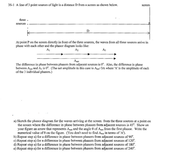
Transcribed Image Text:### Phasor Diagram Analysis
**Description:**
The diagram illustrates a basic setup for analyzing wave interference from three point sources of light. These sources are positioned linearly a distance \( D \) from a screen.
At point \( P \) on the screen, directly in front of the sources, the waves are in phase. This is depicted by a phasor diagram showing three phasors \( A_1 \), \( A_2 \), and \( A_3 \) combined to form a single resultant phasor \( A_{\text{net}} \).
#### Phasor Diagram Explanation:
- **Phasors \( A_1 \), \( A_2 \), \( A_3 \):** These represent the amplitude of each wave individually, all in phase at 0°.
- **Resultant Phasor \( A_{\text{net}} \):** The net amplitude \( A_{\text{net}} = 3A \), where \( A \) is the amplitude of each individual phasor. This occurs because the difference in phase between adjacent phasors is 0°.
### Tasks:
#### (a) Phasor Diagram with 45° Phase Difference
- **Diagram Needed:** Sketch a new phasor diagram where each adjacent phasor has a 45° phase difference.
- **Details to Include:** An arrow indicating \( A_{\text{net}} \) with numerical angle \( \theta \) from the first phasor.
#### (b) Phase Difference of 90°
- **Action:** Repeat step (a) for a 90° phase difference.
#### (c) Phase Difference of 120°
- **Action:** Repeat step (a) for a 120° phase difference.
#### (d) Phase Difference of 180°
- **Action:** Repeat step (a) for a 180° phase difference.
#### (e) Phase Difference of 240°
- **Action:** Repeat step (a) for a 240° phase difference.
This exercise helps in understanding the superposition principle and interference patterns resulting from different phase differences.
Expert Solution
This question has been solved!
Explore an expertly crafted, step-by-step solution for a thorough understanding of key concepts.
Step by stepSolved in 2 steps with 5 images

Knowledge Booster
Similar questions
- (Figure 1) shows the light intensity on a screen 2.5 m behind a double slit. The wavelength of the light is 512 nm Part A What is the spacing between the slits? Express your answer to two significant figures and include the appropriate units. HÀ ? d = Value Units Submit Previous Answers Request Answer X Incorrect; Try Again; 9 attempts remaining < Return to Assignment Provide Feedback Figure <) 1 of 1 cm 1' 3' 4arrow_forwardThe diagram below illustrates the phenomenon of "missing orders" in the interference pattern made by a double slit. Some orders are missing (that is, there should be a bright fringe but there isn't) because: "Missing orders" Select one: a. Light reaching the screen that passes through different parts of each slit interferes destructively, even though light from the two slits interferes constructively O b. Light reaching the screen from the two slits interferes destructively, even though light that passes through different parts of each slit interferes constructivelyarrow_forwardKeeping the slit width and screen distance constant, how does the light colour such as blue, red and green affects the fringe spacing. Briefly explain your answers in wordsarrow_forward
- Part A How many slits per centimeter does a grating have if the third-order occurs at an 17.0 ° angle for 620-nm light? Express your answer using three significant figures. Vα ΑΣφ ? slits/cm IIarrow_forwardA. It appears that there should be a bright fringe at the location of point D. Why isn’tthere? Explain The previous figure is also labeled with points A and B which are at the locations of maximaand points C and D which are at the locations of minimum For Questions b and c below,you will need to discuss whether each of those minima/maxima stays at the same location,moves to the left or moves to the right and then explain your answers for each B. The slit width is slightly decreased C. The slit separation is slightly decreased.arrow_forwardThe diagram below shows the wave crests for two sources that are totally in phase. For each of the labeled points, determine whether the light intensity (not the wave amplitude) is a minimum or a maximum. B S, Maximum Minimum Neither Submit Answer Tries 0/100arrow_forward
- Light with a wavelength of 586 nm passes through two slits and forms an interference pattern on a screen 9.05 m away. Part A If the linear distance on the screen from the central fringe to the first bright fringe above it is 5.28 cm, what is the separation of the slits? Express your answer to three significant figures. V5] ΑΣΦ d= pwc ?arrow_forwardSolve the problem applying Young's double split experiment.arrow_forwardQuestion 1arrow_forward
- A 450 lines/mm diffraction grating is illuminated by light of wavelength 520 nm. Part A How many bright fringes are seen on a 3.5-m-wide screen located 2.2 m behind the grating? Express your answer using one significant figure. View Available Hint(s) n = [5] ΑΣΦ ?arrow_forwardLight with a wavelength of 561 nm passes through two slits and forms an interference pattern on a screen 8.70 m away. Part A If the linear distance on the screen from the central fringe to the first bright fringe above it is 5.28 cm, what is the separation of the slits? Express your answer to three significant figures. ? d = um Submit Request Answer Provide Feedbackarrow_forward
arrow_back_ios
arrow_forward_ios