Introductory Circuit Analysis (13th Edition)
13th Edition
ISBN: 9780133923605
Author: Robert L. Boylestad
Publisher: PEARSON
expand_more
expand_more
format_list_bulleted
Concept explainers
Question

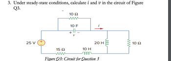
Transcribed Image Text:3. Under steady-state conditions, calculate i and v in the circuit of Figure
Q3.
25 V
+
10 Ω
10 F
+
10 H
m
i
20 H
15 Ω
www
Figure Q3: Circuit for Question 3
ell
10 Ω
Expert Solution
This question has been solved!
Explore an expertly crafted, step-by-step solution for a thorough understanding of key concepts.
Step by stepSolved in 3 steps with 2 images

Knowledge Booster
Learn more about
Need a deep-dive on the concept behind this application? Look no further. Learn more about this topic, electrical-engineering and related others by exploring similar questions and additional content below.Similar questions
- R2 ww C1 I1 R1 L1 R3: .For the circuit shown above, calculate the energy stored in the capacitor C1 Assume 11 = 17 A, R1 = 17 Ohms, R2 = 17 Ohms, R3 = 48 Ohms, L1 = 6 H, and C1 = 15 E .Write your answer in Joulesarrow_forwardanswer the following questions using the attached picture. (c) To measure the current flow though R1 and the voltage onR5, how should we connect the ammeter and voltmeter?Draw a circuit diagram showing your answer. (d) What is the ideal impedance of1). an ammeter?2). a voltmeter?arrow_forwardPlease asaparrow_forward
- Q.2. Find R₁, R₂, and R3 in the following figure when the value of fuse is 20 mA. 5.6 V www R₁ 9 V P₂ = 22 mW R3 10 mA R₂arrow_forwardIn the circuit in the figure R R emf of the battery& = 20 V. All the inductors are of the L 3R. L R same inductance, L=0.05 H and of negligible resistances. Resistances of the resistors %3D %3D %3D are Ro = 3, R1 = 10, R2 = 40, Rg = 49, Ry = 40, Rg = 30, %3D %3D R = 32. The switch S is closed at the time t = 0. %3D What is the current flowing in Ro long after the switch S is closed?arrow_forward1. (a) A DC circuit is shown in Figure 1 and it is working under steady state conditions. R3 22 L1 1m V1 V2 12V 24V R4 22 R1 R2 R5 R6 10 10 47 18 IT Figure 1 (i) Calculate the total current, IT, in the circuit shown in Figure 1. (ii) Calculate the power dissipated in resistors R1, R3, R5 and R6. (iii) How would the total current, IT, change if a capacitor was used instead of L1 under steady state conditions?arrow_forward
- For most of the circuits, determine all the voltages and currents necessary this usually involves:(Eth, VR1, VR2) VB,VC,VE, VCE,VCB, IB, IC,IE, (I'C)arrow_forwardQ3: Suppose that the components of the circuit shown in figure below, have the following values: R1= 162 , R2= 182 , R3=302 , R4=92 , R5= 4Q . The voltage across AB is measured by a voltmeter whose internal resistance is 2502. What is the measurement error caused by the resistance of the measuring instrument? RM 36v T 13 Eo EMarrow_forwardA circuit consisting of three ideal batteries with voltages 1, E2, and E3, and three ideal resistors with resistances R₁, R₂, and R3, is shown in the figure. ₁ 19.0 V, 82 = 21.0 V, E3 = 24.0 V R₁ = 3.90 kQ2, R₂ = 15.5 kQ, R3 = 6.75 k Calculate the current Ip through point P. Let the sign of the current correspond to its direction, with "up" being positive. Ip = P R₁ E₁ + + E2 R₂ www R3 H E3 + mAarrow_forward
- The diagram shows an ideal (zero internal resistance) DC source connected to three identical resitances and a switch. In the diagram, the switch is open. If initially, the switch is open, what happens to current I1 and I2 after the switch is closed?arrow_forwardIn the circuit in the figure emf of the battery&= 20 V. R All the inductors are of the R, L, L same inductance, L=0.05 H and of negligible resistances. Resistances of the resistors %3D %3D %3D are Ro = 32, RỊ = 10, R2 = 42, R = 49, Rq = 40, Rg = 50. %3D %3D R = 30. The switch S is closed at the time t = 0. What is the current flowing in Ro long after the switch S is closed?arrow_forward
arrow_back_ios
arrow_forward_ios
Recommended textbooks for you
 Introductory Circuit Analysis (13th Edition)Electrical EngineeringISBN:9780133923605Author:Robert L. BoylestadPublisher:PEARSON
 Delmar's Standard Textbook Of ElectricityElectrical EngineeringISBN:9781337900348Author:Stephen L. HermanPublisher:Cengage Learning
 Programmable Logic ControllersElectrical EngineeringISBN:9780073373843Author:Frank D. PetruzellaPublisher:McGraw-Hill Education
 Fundamentals of Electric CircuitsElectrical EngineeringISBN:9780078028229Author:Charles K Alexander, Matthew SadikuPublisher:McGraw-Hill Education
 Electric Circuits. (11th Edition)Electrical EngineeringISBN:9780134746968Author:James W. Nilsson, Susan RiedelPublisher:PEARSON
 Engineering ElectromagneticsElectrical EngineeringISBN:9780078028151Author:Hayt, William H. (william Hart), Jr, BUCK, John A.Publisher:Mcgraw-hill Education,

Introductory Circuit Analysis (13th Edition)
Electrical Engineering
ISBN:9780133923605
Author:Robert L. Boylestad
Publisher:PEARSON

Delmar's Standard Textbook Of Electricity
Electrical Engineering
ISBN:9781337900348
Author:Stephen L. Herman
Publisher:Cengage Learning

Programmable Logic Controllers
Electrical Engineering
ISBN:9780073373843
Author:Frank D. Petruzella
Publisher:McGraw-Hill Education

Fundamentals of Electric Circuits
Electrical Engineering
ISBN:9780078028229
Author:Charles K Alexander, Matthew Sadiku
Publisher:McGraw-Hill Education

Electric Circuits. (11th Edition)
Electrical Engineering
ISBN:9780134746968
Author:James W. Nilsson, Susan Riedel
Publisher:PEARSON

Engineering Electromagnetics
Electrical Engineering
ISBN:9780078028151
Author:Hayt, William H. (william Hart), Jr, BUCK, John A.
Publisher:Mcgraw-hill Education,