
Introductory Circuit Analysis (13th Edition)
13th Edition
ISBN: 9780133923605
Author: Robert L. Boylestad
Publisher: PEARSON
expand_more
expand_more
format_list_bulleted
Related questions
Question
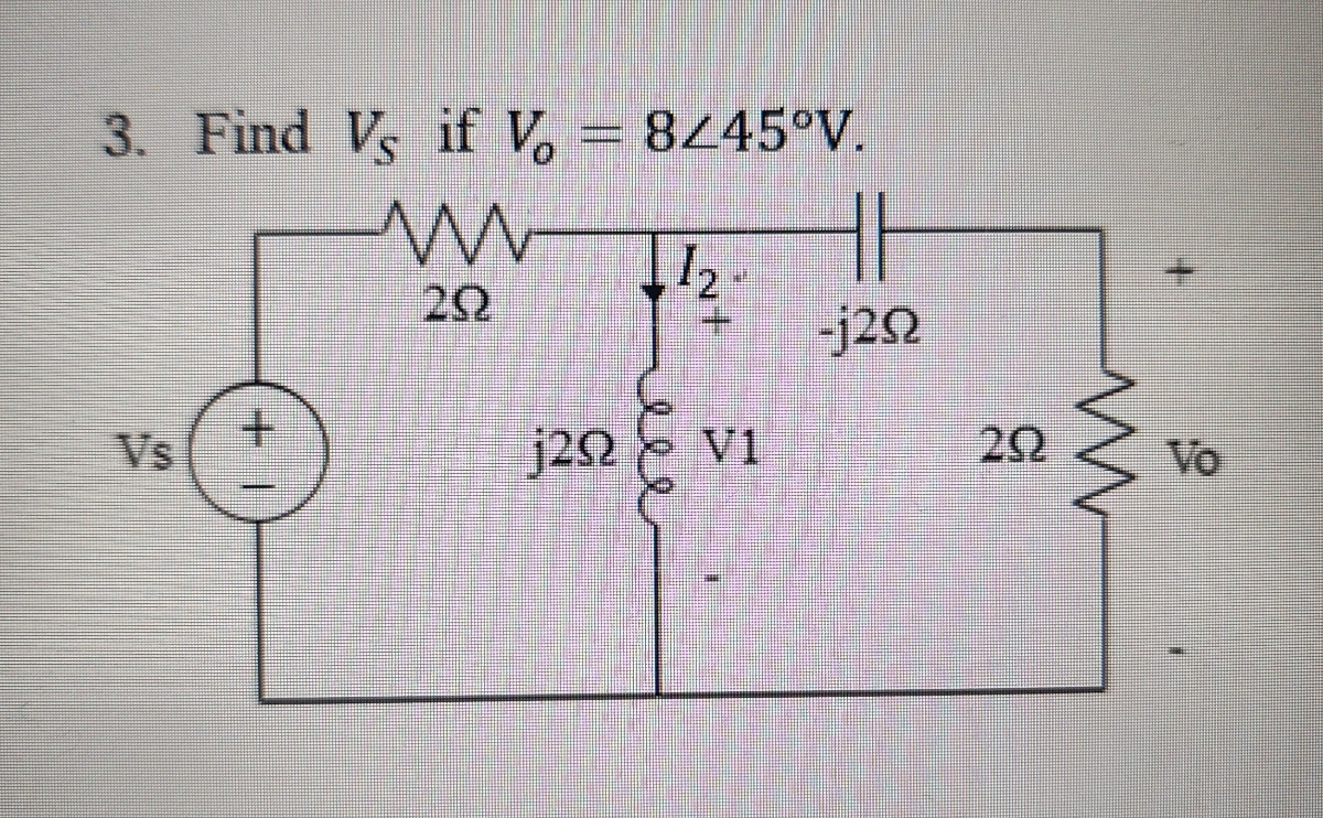

Transcribed Image Text:3. Find Vs if V = 8445°V.
w
20
12
Vs
|+
j20
ele
HH
-j292
V1
20
w
Vo
Expert Solution
This question has been solved!
Explore an expertly crafted, step-by-step solution for a thorough understanding of key concepts.

Step by stepSolved in 1 steps with 2 images

Knowledge Booster

Similar questions
- Find the total impedance of the circuit below. -j5 2 52 100/0 V(A) 50 j4 2 120/13 + j15/13 ohms 150/11 - j12/7 ohms 95/14 - j53/37 ohms O 32/3 - j4/3 ohmsarrow_forward3. Given a series RC circuit with R = 50 Q, Z = 120 Q and has a frequency of 60HZ Find: a. Xc b. C С. О d. Z when f = 30HZ Answer: a. Xc = 109.087 Q b. C = 24.316 uF c. O = 65.376° d. Z = 223.830 Qarrow_forwardfind voarrow_forward
- Evaluate the following complex number and write the magnitude of the resulting number. 82 65⁰ Z 6-j8+ 3260° 2+jarrow_forwardFind the sinusoids corres Pong th Foldowing Pha Sor s I =13/22-61°arrow_forwardUse superposition to find the contribution of each source to the phasor current Io in the circuit shown, and the resulting total current Io- j4 2 32 1 4290° A 6Z-90° varrow_forward
- An Alternating voltage is given by v= 80sin (200rtt – 0.25) the phase angle in degree will be O 14.32 degree lagging O 14.32 degree leading O Zero O 0.25arrow_forwardGraph av(vo/vi) and Theta against frequencyarrow_forwardWith the given delta wye circuit with L=165mH, C=27uF, f=60Hz, R=100Ω, complete the table and find the impedance in rectagular form. Do not round off answer until the final answer. Round off final answer to five decimal places if applicable.arrow_forward
- Given a delta wye circuit with L=265mH, C=27uF, f=60Hz, and R=100Ω, complete the table and find the impedance in rectagular and polar form. Show solutions and do not round off answer until the final answer. Round off final answer to five decimal places if applicable.arrow_forwardFind Zc Z, = 12 + j5 Q ZB Z 2 = 7 – j24 N Z 3 = 8 + j6 N ZAarrow_forwardCircuits 2arrow_forward
arrow_back_ios
SEE MORE QUESTIONS
arrow_forward_ios
Recommended textbooks for you
- Introductory Circuit Analysis (13th Edition)Electrical EngineeringISBN:9780133923605Author:Robert L. BoylestadPublisher:PEARSON
 Delmar's Standard Textbook Of ElectricityElectrical EngineeringISBN:9781337900348Author:Stephen L. HermanPublisher:Cengage Learning
 Programmable Logic ControllersElectrical EngineeringISBN:9780073373843Author:Frank D. PetruzellaPublisher:McGraw-Hill Education
  Fundamentals of Electric CircuitsElectrical EngineeringISBN:9780078028229Author:Charles K Alexander, Matthew SadikuPublisher:McGraw-Hill Education
 Electric Circuits. (11th Edition)Electrical EngineeringISBN:9780134746968Author:James W. Nilsson, Susan RiedelPublisher:PEARSON
 Engineering ElectromagneticsElectrical EngineeringISBN:9780078028151Author:Hayt, William H. (william Hart), Jr, BUCK, John A.Publisher:Mcgraw-hill Education,
Introductory Circuit Analysis (13th Edition)
Electrical Engineering
ISBN:9780133923605
Author:Robert L. Boylestad
Publisher:PEARSON
Delmar's Standard Textbook Of Electricity
Electrical Engineering
ISBN:9781337900348
Author:Stephen L. Herman
Publisher:Cengage Learning
Programmable Logic Controllers
Electrical Engineering
ISBN:9780073373843
Author:Frank D. Petruzella
Publisher:McGraw-Hill Education
Fundamentals of Electric Circuits
Electrical Engineering
ISBN:9780078028229
Author:Charles K Alexander, Matthew Sadiku
Publisher:McGraw-Hill Education
Electric Circuits. (11th Edition)
Electrical Engineering
ISBN:9780134746968
Author:James W. Nilsson, Susan Riedel
Publisher:PEARSON
Engineering Electromagnetics
Electrical Engineering
ISBN:9780078028151
Author:Hayt, William H. (william Hart), Jr, BUCK, John A.
Publisher:Mcgraw-hill Education,