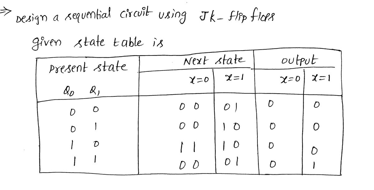
3. Design a sequential circuit specified by Table 6.1, using JK flip-flops. Table 6.1 Present State Qo Q₁ 00 01 10 11 Next State x=0 00 00 1 1 00 X = 1 01 10 10 01 Output X=0 0 0 0 0 x = 1 0
Q: 1 2 Resistance Value 10 Q2 620 Ω First Color Second Color Third Color
A: The resistance, R=10 Ω The resistance, R=620 Ω
Q: For a boost converter operating in continuous conduction mode, when the dc input voltage is 10…
A:
Q: Q4: A: A string of 3 insulators and the ratio of Ce/C = 0.15, if the string is connected to 3- line…
A:
Q: 18. Represent the electrical network shown in state space where V₁ (t) is the output. v(t) (+) 2 H…
A: State variables are choosen as current through the inductor. (Note: if any capacitor found then…
Q: Calculate the equivalent impedance of a circuit in which a coil of wire having a value of 5253.2° is…
A: The circuit is shown below: The impedance of the coil is Z1=5∠53.20 Ω The impedance of the coil in…
Q: 4. Use superposition to find the value of lo in the circuit. 2 ΚΩ 12V(+ +)ον Dov 3 ΚΩ 6 ΚΩ 12V 4 ΚΩ…
A:
Q: 2.) Obtain the unit-impulse response and the unit-step response of a unity-feedback system whose…
A:
Q: A. B C. D. A = 1, B = 0, C = 0, D = 1 F
A: The output of AND gate is high if all the input is high. The output of OR gate is high if any one of…
Q: Find Vout 10.0 V 2 k 2 k M Vout
A: This is a basic problem of circuit. The solution is given in the next step
Q: A 110V d.c. generator supplies a lighting load of forty 100W bulbs, a heating load of 10 kW and…
A: Generally loads are connected in parallel to maintain constant voltage across it. Based on load…
Q: A receiver is tuned to an RF signal of 96 MHz and the LO frequency is 100 104 MHz O 108 MHz 98 MHz…
A: Given data, RF signal frequency, fs=96 MHz. Local oscillator frequency, fl=100 MHz.
Q: For the 13-kVA, 1540/220-V transformer shown in Figure (2): a) Calculate the full-load voltage…
A: Given, E1 = 1540 VE2 = 220 V Z1 = 4.4 + j6.5 ΩZ2 = 0.042 + j0.048 Ω Where, R1 = 4.4 ΩR2 = 0.042 Ω…
Q: Zero Flag explained in a few lines
A: Zero Flag is a bit in flag register. It says whether the output of an operation is zero or not by…
Q: Problem-4) Two-watt meters, which are connected to measure the total power on a three-phase system…
A: Given data- 2 watt meters, Readings=10.5 kW & 2.5 kW. To Find- The power factor of the circuit.
Q: 3. Solve the equivalent resistance across: a. "a" and "b" b. "c" and "d" 30 3Q 202 NEZ C 40 652 a 30…
A:
Q: Calculate the output voltage if V₁ = 1.09V, and V₂ = 0.59V. Vo=____V 250 ΚΩ 500 ΚΩ 100 kn 50 kn 500…
A: We need to find out the output voltage for given op amp circuit .the given circuit is the inverting…
Q: 5² +35+k 25³ +45² +55 Find the value of k that makes the final value of the system output 38 The…
A: Given, Ys=s2+3s+k2s3+4s2+5s final value=38 k = ?
Q: Problem 7 Assume that the given circuit is at steady state before the switch opens at time t = 0.…
A:
Q: 2. Calculate the total resistance between the points A and B. чит 1 ohm A ww 4 ohm www 2 ohm
A: Given data, Circuit diagram is given as,
Q: V = ? (± 3.2 5 2 5 + Vx = 9V
A: given circuit
Q: What would be the barrier potential of a silicon diode when the junction temperature is at 50°C?…
A:
Q: B-5-8. Referring to the system shown in Figure 5-75, de- termine the values of K and k such that the…
A:
Q: Q5: Design an Armstrong indirect FM modulation to generate an FM signal with carrier frequency 97.3…
A: Given Frequency of carrier signal fc=97.3 KHz output frequency of NBFM, fc1=2KHz ∆f=5KHz Range of…
Q: Given the logic circuit, determine the Boolean expression of the output and simplify to a minimum…
A:
Q: An analog signal is to be coded by an ADC. The signal contains significant frequencies up to 3.2kHz.…
A: We need to analyse the given sampled signal , we need to find out sampling frequency and number of…
Q: A self-inductance of 10 mH and its resistance 5 connect to AC source of voltage 200 V, and frequency…
A: The impedance of the circuit is, Z=R+jωLR=5 ΩL=10 mHω=2πfω=120πZ=5+j120π×10×10-3 ΩZ=5+j3.77…
Q: A coil has an ac voltage of 120 V. The current through the coil is 104-85° A What is the inductive…
A:
Q: Types of DC Generators 1. The armature of a separately-excited DC generator has 0.06 effective…
A:
Q: If the maximum analog frequency is 50Hz, the minimum sampling frequency to avoid aliasing is 75Hz…
A:
Q: 1. Count the number of branches and nodes in the circuit of Figure A. If i、 = 3A, and the 18V source…
A:
Q: Q4: A: A string of 3 insulators and the ratio of Ce/C = 0.15, if the string is connected to 3- line…
A: Given data, No. of insulators n=3 Current Ic=CeC=0.15 Line voltage VL=33000 V
Q: You have conducted an experiment, a 20 uF capacitor, a 45 W lamp, a 0.6 H inductor with 35 ohm…
A: Given: You have conducted an experiment, a 20 μF capacitor, a 45 W lamp, a 0.6 H inductor with…
Q: In the network shown in the figure, each of the resistance is equal to 20. The resistance between…
A: Delta to star conversion- Ra=RabRacRab+Rbc+RacRb=RabRbcRab+Rbc+RacRc=RbcRacRab+Rbc+Rac
Q: 38mA Іг 2КЛ 4кл V, 5 КЛ 4 кл
A:
Q: SECTION 15.4 Capacitive Elements 6. For the capacitive element of Fig. 15.86: a. Write the voltage…
A: Note: Since we only answer up to 3 sub-parts, we’ll answer the first 3. Please resubmit the question…
Q: Consider an anti-aliasing filter design using the Butterworth filter. The anti-aliasing filter feeds…
A: According to the question, Consider an anti-aliasing filter design using the Butterworth filter. The…
Q: B) 1. The reflection coefficient is equal to (1) when: a) Z₁-0 b) Z,₁=0⁰ c) Z₁-Zo d) Z,=1
A:
Q: QUESTION 3 A coil has an ac voltage of 120 V. The current through the coil is 10 4-85° A What is the…
A: (3) It is given that: Vac=120 VI=10∠-85° A
Q: A resistance of the coil is 500 and the number of turns 200 turns, connecting in a row with a…
A:
Q: 3. A bode plot of (1+jWT) has a) Slope of 20dB/decade and phase angle of tan ¹(wT) b) Slope of…
A: We need to find out the slope and phase for given transfer function .
Q: Convert the number -3410 to IEEE-754 floating point. Include only the first 6 bits of
A: The floating point numbers are represented by IEEE-754 standard format. It can be single precision…
Q: Compute for the resistance value. Show your solution
A: Color coding is a method used to identify the value of resistors. The number of the color bands may…
Q: total amount of power in the series circuit. 50 V- 52 2Ω 18 2Ω
A: Voltage = 50 V Resistance R1 = 5Ω Resistance R2 = 2Ω Resistance R3 = 1Ω Resistance R4 = 2Ω
Q: A 4-pole shunt generator with a lap-wound armature has an armature resistance of 0.1 ohm, and field…
A:
Q: Q2: Fill in the blanks for the following 1- The main steps of communication system are 2- The…
A:
Q: Find the equivalent resistance of the network shown in figure between the points a and b O (b)
A: We need to find out the equivalent resistance for given circuit ,. We will use series and parallel…
Q: The voltage Vo in the circuit shown equals 104 SA ίδιο 200 ξ 200 ἦν. ЗА
A: Given data, Circuit diagram is given as,
Q: 4. Solve the equivalent resistance across "x" and "y". X 362 2Q 62 M 12. 2Q 42 62. Y
A:
Q: ROBLEM #7 MAKING APPROPRIATE USE OF RESISTOR COMBINATION TECHNIQUES, CALCULATE is AND UY IN THE…
A:
Q: 4. In an Amplitude Modulation: a) Amplitude of the carrier varies. b) Frequency of the carrier…
A: Amplitude Modulation Amplitude modulation is a type of modulation used in electronic communication,…
hi please solve this problem in short way asap
Step by step
Solved in 4 steps with 4 images
- Electrical Engineering Verilog Design N-bit binary counter which counts the number from 0 to 2N-1. After reaching to maximum count i.e. 2N-1, it again starts the count from 0. i. Write the description of the counter in Verilog ii. Generate the design from the listing ii. Produce the waveforms of the counterFrom the BCD code whose block diagram is given in the figure below, you can find the 7-segment LED display (with common anode) code. Solving combinational logic circuit will be designed. This type of commercially produced decoder is integrated State the features you consider important by researching the circuits. BCD input at the output of the decoder For the 0-9 values of the information information, the following display figures will be seen and the values other than these it will be considered arbitrary. Since the 7-segment LED display has a common anode, Logic "0" will be applied in response to the burned parts. The accuracy of the logic circuit you will design Create the table and find the output expressions by shrinking the table with the Karnaugh diagram method.From the BCD code whose block diagram is given in the figure below, you can find the 7-segment LED display (with common anode) code. Solving combinational logic circuit will be designed. This type of commercially produced decoder is integrated State the features you consider important by researching the circuits. BCD input at the output of the decoder For the 0-9 values of the information information, the following indicator figures will be seen and the values other than these it will be considered arbitrary. Since the 7-segment LED display has a common anode, The logic "0" will be applied to the burned parts. Draw this circuit.
- From the BCD code whose block diagram is given in the figure below, you can find the 7-segment LED display (with common anode) code. Solving combinational logic circuit will be designed. This type of commercially produced decoder is integrated State the features you consider important by researching the circuits. BCD input at the output of the decoder For the 0-9 values of the information information, the following indicator figures will be seen and the values other than these it will be considered arbitrary. Since the 7-segment LED display has a common anode, Logic "0" will be applied to the burned parts. The accuracy of the logic circuit you will design Create the table and find the output expressions by shrinking the table with the Karnaugh diagram method.USE DIGITAL LOGIC AND DESIGN Part 1: In Figure_4; we have 4-bit Comparator using 2-bit Comparators block. You have to satisfy given condition by applying all data on figure 4. At the end, given condition should produce HIGH output and other two should be LOW. A3 A2 A1 A0 = 1101 and B3 B2 B1 B0 = 1110 Figure_4 Part 2: The serial data-input waveform (Data in) and data-select inputs (S0 and S1) are shown in Figure_5. Determine the data-output waveforms from D0 through D3. Figure_5 Part 3: Decoder can be useful when we have to decode some specific numbers from their equivalent code. Figure 6 has a concept of 3 to 8 line decoder from which you have to generate output waveform from D0 to D7 with proper relationship to input. Figure_6 Part 4: The data-input and…Design the interfacing circuit shown below and write a program to display single digit (between 0 and 9) prime numbers followed by even numbers, the next odd numbers and repeats in 7-segment displays and its equivalent 8-bit binary value in LEDS. a) When displaying Prime numbers, the first 7-segment display must show "P" and the second 7-segment display must show prime numbers one by one b) When displaying Even numbers, the first 7-segment display must show "E" and the second 7-segment display must show even numbers one by one c) When displaying Odd numbers, the first 7-segment display must show "O" and the second 7-segment display must show even numbers one by one
- H.W :- 1) A four logic-signal A,B,C,D are being used to represent a 4-bit binary number with A as the LSB and D as the MSB. The binary inputs are fed to a logic circuit that produces a logic 1 (HIGH) output only when the binary number is greater than 01102-610. Design this circuit. 2) repeat problem 1 for the output will be 0 (LOW) when the binary input is less than 01112-710- Saleem LateefDesign the following combinational logic circuit with a four-bit input and a three-bit output. The input represents two unsigned 2-bit numbers: A1 A0 and B1 B0. The output C2 C1.C0 is the result of the integer binary division A1 A0/B1 B0 rounded down to three bits. The 3-bit output has a 2-bit unsigned whole part C2 C1 and a fraction part CO. The weight of the fraction bit CO is 21. Note the quotient should be rounded down, i.e. the division 01/11 should give the outputs 00.0 (1/3 rounded down to 0) not 00.1 (1/3 rounded up to 0.5). A result of infinity should be represented as 11.1. A minimal logic implementation is not required. (Hint: start by producing a truth table of your design).Q6: For the following logic function: F(x,y,z) = xyz + xyz + xyz +xyz a. Draw the logic Circuit b. Construct the Truth Table c. Simplify the Logic Circuit
- PLEASE HELP ME , this subject is all about combinational logic design4 7) For the following sequential circuit: a) Tabulate the state table. b) Derive the state and output equations. c) Re-design the circuit using T flip-flops. Q1 Q -y K, K QP Jo Qo Q Ko K Q clock. please solve it as soon as possibleDIGITAL LOGIC DESIGN Are the following addition results Overflow or underflow and why?