
Introductory Circuit Analysis (13th Edition)
13th Edition
ISBN: 9780133923605
Author: Robert L. Boylestad
Publisher: PEARSON
expand_more
expand_more
format_list_bulleted
Related questions
Question
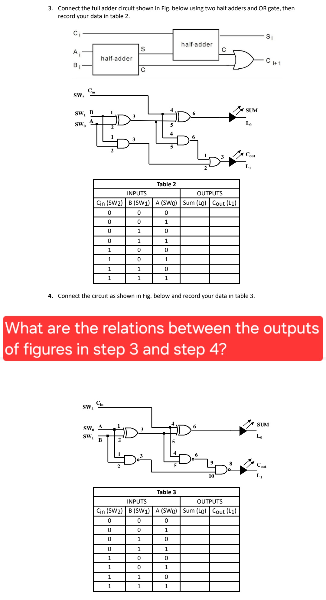

Transcribed Image Text:3. Connect the full adder circuit shown in Fig. below using two half adders and OR gate, then
record your data in table 2.
Ci
Si
half-adder
S
C
A
half-adder
Bi
C
Cin
SW2
SW₁ B
SWO
3
2
Table 2
INPUTS
OUTPUTS
Cin (SW2) B (SW1) A (SWO) Sum (LO) Cout (L1)
0
0
0
0
0
1
0
1
0
0
1
1
1
0
0
1
0
1
1
1
0
1
1
1
SUM
Lo
Cout
L₁
4. Connect the circuit as shown in Fig. below and record your data in table 3.
i+1
What are the relations between the outputs
of figures in step 3 and step 4?
SW2
Cin
SWO
A
SW₁
B
6
3
Table 3
10
SUM
Lo
8
Cout
L₁
INPUTS
OUTPUTS
Cin (SW2) B (SW1) A (SWO) Sum (L0) Cout (L1)
0
0
0
0
0
1
0
1
0
0
1
1
1
0
0
1
0
1
1
1
0
1
1
1
Expert Solution
This question has been solved!
Explore an expertly crafted, step-by-step solution for a thorough understanding of key concepts.

Step by stepSolved in 2 steps with 3 images

Knowledge Booster

Similar questions
- 30 For the circuit attached:Give the AND-OR expression as it is shown (No Spaces in your expression w'y+yz' not w'y + yz') (List from the top AND gate to the bottom AND gate)Draw a K-Map for it (Do not attach the K-Map) Give the minimum AND-OR expression for itarrow_forwardThis is a practice problem I am having a little difficulty with understanding. Thank you for the help.arrow_forwardUsing the K map simplify logic expression Fand draw an AOl circuit. Attach picture of your work here. Q R S F5 1 1 QR 1 110 1000 1 1 QR QR 1 1 1 QR 1 1 1 1arrow_forward
- For the chip below, determine the selection S2S1S0 that will generate a 1 at the Y output for the input conditions: I = 1z16l5|4|3|21110 = 00000100. Assume the device is enabled to have normal operation. U3 74LS151 EO- S2 S1 SO 15 14 H13 12 I0 YNO- 100 O_001 111 O 010 1654 3210 HHHH H H HEarrow_forwardanswer both questionsarrow_forward
arrow_back_ios
arrow_forward_ios
Recommended textbooks for you
- Introductory Circuit Analysis (13th Edition)Electrical EngineeringISBN:9780133923605Author:Robert L. BoylestadPublisher:PEARSON
 Delmar's Standard Textbook Of ElectricityElectrical EngineeringISBN:9781337900348Author:Stephen L. HermanPublisher:Cengage Learning
 Programmable Logic ControllersElectrical EngineeringISBN:9780073373843Author:Frank D. PetruzellaPublisher:McGraw-Hill Education
  Fundamentals of Electric CircuitsElectrical EngineeringISBN:9780078028229Author:Charles K Alexander, Matthew SadikuPublisher:McGraw-Hill Education
 Electric Circuits. (11th Edition)Electrical EngineeringISBN:9780134746968Author:James W. Nilsson, Susan RiedelPublisher:PEARSON
 Engineering ElectromagneticsElectrical EngineeringISBN:9780078028151Author:Hayt, William H. (william Hart), Jr, BUCK, John A.Publisher:Mcgraw-hill Education,
Introductory Circuit Analysis (13th Edition)
Electrical Engineering
ISBN:9780133923605
Author:Robert L. Boylestad
Publisher:PEARSON
Delmar's Standard Textbook Of Electricity
Electrical Engineering
ISBN:9781337900348
Author:Stephen L. Herman
Publisher:Cengage Learning
Programmable Logic Controllers
Electrical Engineering
ISBN:9780073373843
Author:Frank D. Petruzella
Publisher:McGraw-Hill Education
Fundamentals of Electric Circuits
Electrical Engineering
ISBN:9780078028229
Author:Charles K Alexander, Matthew Sadiku
Publisher:McGraw-Hill Education
Electric Circuits. (11th Edition)
Electrical Engineering
ISBN:9780134746968
Author:James W. Nilsson, Susan Riedel
Publisher:PEARSON
Engineering Electromagnetics
Electrical Engineering
ISBN:9780078028151
Author:Hayt, William H. (william Hart), Jr, BUCK, John A.
Publisher:Mcgraw-hill Education,