
Introductory Circuit Analysis (13th Edition)
13th Edition
ISBN: 9780133923605
Author: Robert L. Boylestad
Publisher: PEARSON
expand_more
expand_more
format_list_bulleted
Related questions
Question

Transcribed Image Text:R₁
(10 m)
0.2 H
ми
00000
&₁ = 50V
R₂
(200)
E₂ = 30V

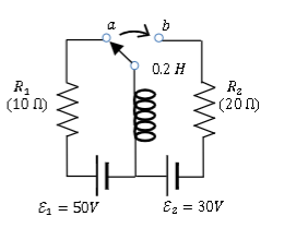
Transcribed Image Text:3. Assume the values given in the circuit diagram above. The switch is in position (a) for a long time before being thrown
into position (b). The switch is designed to make the contact at (b) before breaking the contact at fa) and the inductor is
ideal.
a. What is the magnitude and direction of the current (up/down/zero) through the inductor right after the switch
is thrown? (hint: use Ohm's law)
b. What is the magnitude and direction (up/down/zero) of the EMF induced in the inductor right after the switch is
thrown? (Hint: use the loop rule.)
The answer is not 30V, 50V, 80V or 100V.
c. What is the magnitude and direction of the current (up/down/zero) through the inductor a long time after the
switch is thrown? (Hint: the inductor acts like a short)
Expert Solution
This question has been solved!
Explore an expertly crafted, step-by-step solution for a thorough understanding of key concepts.
Step 1: State the given data
VIEW Step 2: a. Finding the magnitude and direction of the current (up/down/zero) through the inductor at t=0-.
VIEW Step 3: Finding the magnitude and direction of the current (up/down/zero) through the inductor at t=0+.
VIEW Step 4: b. Finding the magnitude and direction (up/down/zero) of the EMF induced in the inductor at t=0+.
VIEW Step 5: c. Finding he magnitude and direction of the current (up/down/zero) through the inductor at t=∞.
VIEW Solution
VIEW 
Step by stepSolved in 6 steps with 14 images

Knowledge Booster


Learn more about
Need a deep-dive on the concept behind this application? Look no further. Learn more about this topic, electrical-engineering and related others by exploring similar questions and additional content below.Similar questions
- 4. Assume the Blue LED has a forward turn on voltage of 4 V and exhibits ideal diode behavior. For the circuit below, sketch the voltage across the diode and the voltage across the resistor (versus time) for the following Vin values. On your waveforms, indicate the time periods when the LED is on. a. Vin= 3 sin(2π *60t) V b. Vin = 5 sin(2π *60t) V Blue LED # Vin 1k R2arrow_forwardCan you help me solve this and explain clearly I saw some answers on chegg but I don’t understand it .arrow_forwardASAP plzarrow_forward
- Please solve this question quecklyarrow_forwardVi (t) = 10.sinwt Does not pass positive alternans when Volt input voltage is applied, only Design and explain two different circuits that pass negative alternans. Draw the input and output voltages. What are the types of these circuits? (Note: You can use the ideal diode approach)arrow_forwardGive an approximate sketch of the expected voltage waveform vi(t) for the circuit shown in Figure 7. The source produces a sinusoidal waveform with a maximum voltage of 12.6 V. Assume that the diode has a turn-on voltage of 0.7 V and that the reverse saturation current is approximately zero. 12.6 V AC 2 ΚΩ C Figure 7- Half-Wave Rectifier Now suppose a capacitor C is connected in parallel with the load as in Figure 8. Calculate a suitable value for C so that the RC time constant is about ~ 0.02 seconds. -2 ΚΩ + Give an approximate sketch of the expected v₁(t) waveform when C is added to the circuit. Qualitatively speaking, what is the role of a capacitor in this circuit? + VL VL VL volts VL voltsarrow_forward
arrow_back_ios
arrow_forward_ios
Recommended textbooks for you
- Introductory Circuit Analysis (13th Edition)Electrical EngineeringISBN:9780133923605Author:Robert L. BoylestadPublisher:PEARSON
 Delmar's Standard Textbook Of ElectricityElectrical EngineeringISBN:9781337900348Author:Stephen L. HermanPublisher:Cengage Learning
 Programmable Logic ControllersElectrical EngineeringISBN:9780073373843Author:Frank D. PetruzellaPublisher:McGraw-Hill Education
  Fundamentals of Electric CircuitsElectrical EngineeringISBN:9780078028229Author:Charles K Alexander, Matthew SadikuPublisher:McGraw-Hill Education
 Electric Circuits. (11th Edition)Electrical EngineeringISBN:9780134746968Author:James W. Nilsson, Susan RiedelPublisher:PEARSON
 Engineering ElectromagneticsElectrical EngineeringISBN:9780078028151Author:Hayt, William H. (william Hart), Jr, BUCK, John A.Publisher:Mcgraw-hill Education,
Introductory Circuit Analysis (13th Edition)
Electrical Engineering
ISBN:9780133923605
Author:Robert L. Boylestad
Publisher:PEARSON
Delmar's Standard Textbook Of Electricity
Electrical Engineering
ISBN:9781337900348
Author:Stephen L. Herman
Publisher:Cengage Learning
Programmable Logic Controllers
Electrical Engineering
ISBN:9780073373843
Author:Frank D. Petruzella
Publisher:McGraw-Hill Education
Fundamentals of Electric Circuits
Electrical Engineering
ISBN:9780078028229
Author:Charles K Alexander, Matthew Sadiku
Publisher:McGraw-Hill Education
Electric Circuits. (11th Edition)
Electrical Engineering
ISBN:9780134746968
Author:James W. Nilsson, Susan Riedel
Publisher:PEARSON
Engineering Electromagnetics
Electrical Engineering
ISBN:9780078028151
Author:Hayt, William H. (william Hart), Jr, BUCK, John A.
Publisher:Mcgraw-hill Education,