Structural Analysis
6th Edition
ISBN: 9781337630931
Author: KASSIMALI, Aslam.
Publisher: Cengage,
expand_more
expand_more
format_list_bulleted
Question

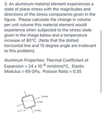
Transcribed Image Text:3. An aluminum material element experiences a
state of plane stress with the magnitudes and
directions of the stress components given in the
figure. Please calculate the change in volume
per unit volume this material element would
experience when subjected to the stress state
given in the image below and a temperature
increase of 80°C. (Note that the dotted
horizontal line and 15 degree angle are irrelevant
to this problem).
Aluminum Properties: Thermal Coefficient of
Expansion = 24 x 10-6 mm/mm/°C, Elastic
Modulus = 69 GPa, Poisson Ratio = 0.35
250 MPa
60 MPa
15°
150 MPa
Expert Solution
This question has been solved!
Explore an expertly crafted, step-by-step solution for a thorough understanding of key concepts.
This is a popular solution
Trending nowThis is a popular solution!
Step by stepSolved in 2 steps with 2 images

Knowledge Booster
Learn more about
Need a deep-dive on the concept behind this application? Look no further. Learn more about this topic, civil-engineering and related others by exploring similar questions and additional content below.Similar questions
- The stress-strain diagram for a steel alloy having an original diameter of 0.5 in. and a gage length of 2 in. is given in the figure. If the specimen is loaded until it is stressed to 70 ksi, determine the approximate amount of elastic recovery and the increase in the gage length after it is unloaded. o (ksi) 80 70 60 50 40 30 20 10 e (in./in.) 0 04 0.08 0.12 0.16 0.20 0.24 0.28 0 0005 0.0010.0015 0.002 0.0025 0.0030.0035arrow_forwardA circular bar of magnesium alloy is 390 mm long. The stress-strain diagram for the material is shown in the figure. 70 63 56 49 O (MPa) 42 35 28 21 14 7 0.002 0.004 0.006 0.008 0.01 The bar is loaded in tension to an elongation of 2.34 mm, and then the load is removed. Hint: Use the concepts illustrated in the figures below. (Assume the curve in the figure above is linear between (0, 0) and (0.001, 28), and curves with a gradually decreasing slope otherwise.) F В E F Loading CD Loading Residual Elastic strain recovery (a) What is the permanent set of the bar (in mm)? 2.184 X mm (b) If the bar is reloaded, what is the proportional limit (in MPa)? 55 X MPaarrow_forwardFor material, the modulus of rigidity is 100 GPa and the modulus of elasticity is 250 GPa. The value of the Poisson's ratio isarrow_forward
- 2. A steel bar, whose cross section is 0.55 inch by 4.05 inches, was tested in tension. An axial load of P = 30,500 lb. produced a deformation of 0.105 inch over a gauge length of 2.05 inches and a decrease of 0.0075 inch in the 0.55-inch thickness of the bar. Determine the lateral strain. * Your answer Determine the axial strain. Your answer Determine the Poisson's ratio v. * Your answer Determine the decrease in the 4.05-in. cross-sectional dimension (in inches). * Your answerarrow_forwardThe assembly shown in the figure consists of an aluminum tube AB and a steel rod BC. The rod is attached to the tube through the rigid collar at B and passes through the tube. The cross-sectional area of the rod is 75 mm2 and the cross-sectional area of the tube is 400 + UV in mm2, where UV is 99. A tensile load of 80 kN is applied to the rod. Take Est = 200 GPa for the steel rod, Eal = 70 GPa for the aluminum tube. Determine: (a) the displacement of end C with respect to end B (i.e., the elongation of the steel rod), (b) the displacement of end B with respect to the fixed end A (i.e., the shrink of the aluminum tube), (c) the displacement of the end C of the rod (i.e., (a) + (b)).arrow_forwardA round steel alloy bar with a diameter of 19mm and a gauge length of 76mm was subjected to tension, with the results shown in Table. Using a computer spreadsheet program, plot the stress–strain relationship. From the graph, determine the Young’s modulus of the steel alloy and the deformation corresponding to a 37kN load.arrow_forward
- An aluminum rod is rigidly attached between a steel rod and a bronze rod as shown below. Axial loads are applied at the positions indicated. Find the maximum value of P in Newton that will not exceed a stress in steel of 150 MPa, in aluminum of 87 MPa, or in bronze of 97 MPa.arrow_forwardKindly include the diagram. Handwritten solution recommended.arrow_forwardKnowing that a 0.02in gap exists when the temperature is 75°F, determine (a) the temperature at which the normal stress in the aluminum bar will be equal to -11ksi, (b) the corresponding exact length (2 decimal places in 103 inches) of the aluminum bar. 0.02 in. 14 in. Bronze A = 2.4 in² E = 15 × 106 psi a = 12 x 10-6/°F 18 in. Aluminum A = 2.8 in² E = 10.6 × 10⁶ psi a = 12.9 x 10⁻⁶/°Farrow_forward
arrow_back_ios
arrow_forward_ios
Recommended textbooks for you

 Structural Analysis (10th Edition)Civil EngineeringISBN:9780134610672Author:Russell C. HibbelerPublisher:PEARSON
 Principles of Foundation Engineering (MindTap Cou...Civil EngineeringISBN:9781337705028Author:Braja M. Das, Nagaratnam SivakuganPublisher:Cengage Learning
 Fundamentals of Structural AnalysisCivil EngineeringISBN:9780073398006Author:Kenneth M. Leet Emeritus, Chia-Ming Uang, Joel LanningPublisher:McGraw-Hill Education
 Traffic and Highway EngineeringCivil EngineeringISBN:9781305156241Author:Garber, Nicholas J.Publisher:Cengage Learning


Structural Analysis (10th Edition)
Civil Engineering
ISBN:9780134610672
Author:Russell C. Hibbeler
Publisher:PEARSON

Principles of Foundation Engineering (MindTap Cou...
Civil Engineering
ISBN:9781337705028
Author:Braja M. Das, Nagaratnam Sivakugan
Publisher:Cengage Learning

Fundamentals of Structural Analysis
Civil Engineering
ISBN:9780073398006
Author:Kenneth M. Leet Emeritus, Chia-Ming Uang, Joel Lanning
Publisher:McGraw-Hill Education


Traffic and Highway Engineering
Civil Engineering
ISBN:9781305156241
Author:Garber, Nicholas J.
Publisher:Cengage Learning