Introductory Circuit Analysis (13th Edition)
13th Edition
ISBN: 9780133923605
Author: Robert L. Boylestad
Publisher: PEARSON
expand_more
expand_more
format_list_bulleted
Concept explainers
Question

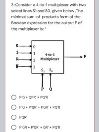
Transcribed Image Text:3-Consider a 4-to-1 multiplexer with two
select lines S1 and SO, given below ,The
minimal sum-of-products form of the
Boolean expression for the output F of
the multiplexer is: *
0-
1-
1
4-to-1
F
R-
2
Multiplexer
R-
3
S, So
O P'Q + QPR' + PQ'R
P'Q + P'QR' + PQR' + PQ'R
PQR'
O P'QR + P'QR' + QR' + PQ'R
Expert Solution
This question has been solved!
Explore an expertly crafted, step-by-step solution for a thorough understanding of key concepts.
This is a popular solution
Trending nowThis is a popular solution!
Step by stepSolved in 2 steps with 2 images

Knowledge Booster
Learn more about
Need a deep-dive on the concept behind this application? Look no further. Learn more about this topic, electrical-engineering and related others by exploring similar questions and additional content below.Similar questions
- A. There are several approaches of the application of various coverage criteria in Generators. Please explain an approach by a simple example. B. How the application of coverage criteria in Generators is different from their usage in Recognizers? How they are used in Recognizers?arrow_forwardDesign and implement a 2-bit integer division circuit. The circuit has four inputs A1,A0,B1,B0 and five outputs Q1,Q0,R1,R0,E. The values on A1,A0,B1,and B0 are treated as unsigned binary integer number A and B respectively. The circuit should generate the quotient Q and remainder R of the division A/B on lines Q1,Q0,R1,R0 respectively. If division by zero is attempted, line E is set '1' otherwise E is '0' and the values on lines Q1,Q0,R1,R0 are considered invalid (If division by zero is attempted). Document the following: 1.specify the truth table for the circuit 2.derive necessary boolean equations (kmaps) 3.draw gate-level logic diagram (logic gate symbols)arrow_forwardq2 carrow_forward
- microprocessorarrow_forwardDesign a Moore state machine with one input x, and one output y. The output is normally 0, but becomes 1 whenever the machine detects the sequence "x = 0", "x = 1", and "x = 1" on the three consecutive rising edges of the clock. Sketch a state graph for your design. Write down the state table for your design Come up with a state assignment Find the excitation logic for D flip flips Sketch a diagram of your final design.arrow_forward
arrow_back_ios
arrow_forward_ios
Recommended textbooks for you
 Introductory Circuit Analysis (13th Edition)Electrical EngineeringISBN:9780133923605Author:Robert L. BoylestadPublisher:PEARSON
 Delmar's Standard Textbook Of ElectricityElectrical EngineeringISBN:9781337900348Author:Stephen L. HermanPublisher:Cengage Learning
 Programmable Logic ControllersElectrical EngineeringISBN:9780073373843Author:Frank D. PetruzellaPublisher:McGraw-Hill Education
 Fundamentals of Electric CircuitsElectrical EngineeringISBN:9780078028229Author:Charles K Alexander, Matthew SadikuPublisher:McGraw-Hill Education
 Electric Circuits. (11th Edition)Electrical EngineeringISBN:9780134746968Author:James W. Nilsson, Susan RiedelPublisher:PEARSON
 Engineering ElectromagneticsElectrical EngineeringISBN:9780078028151Author:Hayt, William H. (william Hart), Jr, BUCK, John A.Publisher:Mcgraw-hill Education,

Introductory Circuit Analysis (13th Edition)
Electrical Engineering
ISBN:9780133923605
Author:Robert L. Boylestad
Publisher:PEARSON

Delmar's Standard Textbook Of Electricity
Electrical Engineering
ISBN:9781337900348
Author:Stephen L. Herman
Publisher:Cengage Learning

Programmable Logic Controllers
Electrical Engineering
ISBN:9780073373843
Author:Frank D. Petruzella
Publisher:McGraw-Hill Education

Fundamentals of Electric Circuits
Electrical Engineering
ISBN:9780078028229
Author:Charles K Alexander, Matthew Sadiku
Publisher:McGraw-Hill Education

Electric Circuits. (11th Edition)
Electrical Engineering
ISBN:9780134746968
Author:James W. Nilsson, Susan Riedel
Publisher:PEARSON

Engineering Electromagnetics
Electrical Engineering
ISBN:9780078028151
Author:Hayt, William H. (william Hart), Jr, BUCK, John A.
Publisher:Mcgraw-hill Education,