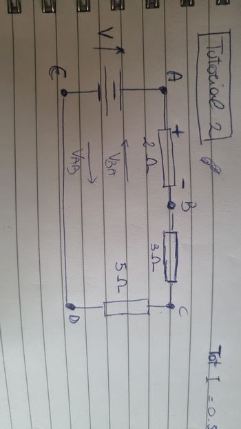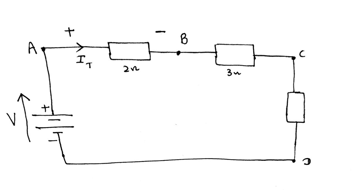
I am aware this should be a simple concept, but it is confusing me instead. I read what you said multiple times and also researched on Google. As I have a test coming up I really want to understand this as otherwise I won't be able to do complex calculations. Could you please try to explain that again? I understand the arrow showing in the circuit diagram refers to the Vsource and not the current, however I know the current goes in the clockwise direction as conventionally the current moves from a positive to a negative zone. As the arrow of the Vsource goes upward, I know the top of the arrow is the positive zone and the bottom is the negative so that's why the current flows clockwise.
I want to take as an example the resistor present in between points A and B. As the current flows from a positive to a negative region, I know that on the left there is going to be a positive sign and on the left a negative sign. That's why I thought that the Vab (which comes from the positive side of the resistor) was positive and Vba negative.
So, I still don't quite understand the voltage direction and sign clearly as this is what I got until now. Could you please tell me one more time why the direction and the sign of voltage between those points are worked out as you did? I really want to understand.


Step by stepSolved in 3 steps with 3 images

- Two hypothetical circuit element (shown by the blue rectangle), are shown in the figure. We will refer to them as the top circuit and the bottom circuit. Determine the best match to the behavior for each circuitarrow_forwardPlease answer this question with as much details possible, so I can understand. This is for Electrical Engineering.arrow_forwardSorry to be a pain, can you break down I2 into further detail. I think I have the understanding now but want to just check. regards stuartarrow_forward
- For given value of the circuit, Vsupply = 120 V, and with R₁= 2002, R₂=30.0, R3=75, R4=30N, R5= 200, R6-400 and R7=12002? • What is the voltage drop across Ro? 1. a) 32 V b) 48V c) 100V d) 120V 2. 48 Volts 100 Volts 32 Volts 120 Volts V1 120 V R1 ww 2002 R3 750 R7 12002 R6 m 40Q R2 2300 R4 30Q R5 2200arrow_forwardINSTRUCTIONS: I really need to understand this. Please follow and I'll give an upvote without any questions. Do not answer if you don't know, please I'm trying to study while working. • If using calculator, please input at the solution. Example: "Just click at 'Mode 2 5" like that • Always write the complete formula including derivation of the fomula • When writing a formula, please input the exact word terminology. Example: Ia = Van/Zan where Ia is a phase A line current • Always put explanation at the computation. TOPIC: Analysis of Balance Polyphase Systems QUESTION: A phase voltage of 230V, 3 phase supply feds a balanced wye-connected load of 10+j5 ohms per phase. The real power of the load is _____ watts.arrow_forwardINSTRUCTIONS: I really need to understand this. Please follow and I'll give an upvote without any questions. Do not answer if you don't know, please I'm trying to study while working. • If using calculator, please input at the solution. Example: "Just click at 'Mode 2 5" like that • Always write the complete formula including derivation of the fomula • When writing a formula, please input the exact word terminology. Example: Ia = Van/Zan where Ia is a phase A line current • Always put explanation at the computation. TOPIC: Analysis of Balance Polyphase Systems QUESTION: A 208V, 3 phase power system is connected through a three-phase transmission line to a Y-connected load. The transmission line has an impedance of 0.06+j0.12 ohms per phase, and the load has an impedance of 12+j9 ohms per phase. For this simple system, find the power factor of the system. (BEP 2015)arrow_forward
- In a house, a circuit often includes multiple electrical outlets which are parallel-connected to a single voltage source. Each of these circuits also contains a 15-A circuit breaker. Design a parallel-connected circuit which shows three electrical outlets con-nected to a voltage source with a circuit breaker. What is the advantage of having out-lets parallel-connected, and why is a circuit breaker connected in series with the voltage source? Why is the circuit breaker considered a necessary safety item in the circuit?arrow_forwardHello Sir,Good Morning I have a question in my home work related mechatronics lesson. The following below is my question. Please advise thank you.arrow_forwardBlock Diagrams Reduces the following systems:arrow_forward
- Shown in the figure below is an electrical circuit containing three resistors and two batteries. I₁ 0= 4 + L . ww R3 R₂ ww 1₂ R₁ ww Write down the Kirchhoff Junction equation and solve it for I, in terms of I₂ and I3. Write the result here: 1₁ = 12-13 R₂=552 R₂ = 132 13 Write down the Kirchhoff Loop equation for a loop that starts at the lower left corner and follows the perimeter of the circuit diagram clockwise. - IzR3 − LR₁ + 14 + 10 Write down the Kirchhoff Loop equation for a loop that starts at the lower left corner and touches the components 4V, R₂, and R₁. 0 = 4-1₂R₂-11R₁ The resistors in the circuit have the following values: R₁ = 12 Solve for all the following (some answers may be negative): I₁ = 27.78 X Amperes 1₂ = 28.84 X Amperes 13 = 1.060 X Amperes NOTE: For the equations, put in resistances and currents SYMBOLICALLY using variables like R₁,R₂,R3 and 11,12,13. Use numerical values of 10 and 4 for the voltages.arrow_forwardPlease click on pic to open itarrow_forwardINSTRUCTIONS: I really need to understand this. Please follow and I'll give an upvote without any questions. Do not answer if you don't know, please I'm trying to study while working. • If using calculator, please input at the solution. Example: "Just click at 'Mode 2 5" like that • Always write the complete formula including derivation of the fomula • When writing a formula, please input the exact word terminology. Example: Ia = Van/Zan where Ia is a phase A line current • Always put explanation at the computation. TOPIC: Power Factor Correction QUESTION: B. It is desired to improve the power factor of a 230V, 60 Hz, 3 phase system from 0.7 to 0.92 lagging. A wye connected capacitor bank with capacitance of 10 microfarad per phase is to be used. What will be the rating of the load in watts?arrow_forward
 Introductory Circuit Analysis (13th Edition)Electrical EngineeringISBN:9780133923605Author:Robert L. BoylestadPublisher:PEARSON
 Delmar's Standard Textbook Of ElectricityElectrical EngineeringISBN:9781337900348Author:Stephen L. HermanPublisher:Cengage Learning
 Programmable Logic ControllersElectrical EngineeringISBN:9780073373843Author:Frank D. PetruzellaPublisher:McGraw-Hill Education
 Fundamentals of Electric CircuitsElectrical EngineeringISBN:9780078028229Author:Charles K Alexander, Matthew SadikuPublisher:McGraw-Hill Education
 Electric Circuits. (11th Edition)Electrical EngineeringISBN:9780134746968Author:James W. Nilsson, Susan RiedelPublisher:PEARSON
 Engineering ElectromagneticsElectrical EngineeringISBN:9780078028151Author:Hayt, William H. (william Hart), Jr, BUCK, John A.Publisher:Mcgraw-hill Education,


