Introductory Circuit Analysis (13th Edition)
13th Edition
ISBN: 9780133923605
Author: Robert L. Boylestad
Publisher: PEARSON
expand_more
expand_more
format_list_bulleted
Concept explainers
Question
thumb_up100%
3-1 to 3-5 and 3-9 to 3-12 please

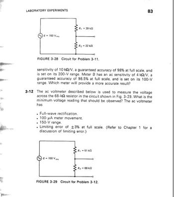
Transcribed Image Text:LABORATORY EXPERIMENTS
E-150
R₁ - 392
R₂-22 k
FIGURE 3-28 Circuit for Problem 3-11.
sensitivity of 10 k/V, a guaranteed accuracy of 98% at full scale, and
is set on its 200-V range. Meter B has an ac sensitivity of 4 k2/V. a
guaranteed accuracy of 98.5% at full scale, and is set on its 100-V
range. Which meter will provide a more accurate result?
8-150
3-12 The ac voltmeter described below is used to measure the voltage
across the 68-k resistor in the circuit shown in Fig. 3-29. What is the
minimum voltage reading that should be observed? The ac voltmeter
has
. Full-wave rectification.
. 100-A meter movement.
. 150-V range.
. Limiting error of ±3% at full scale. (Refer to Chapter 1 for a
discussion of limiting error.)
83
R₁ - 51 k
R₂68 2
FIGURE 3-29 Circuit for Problem 3-12.

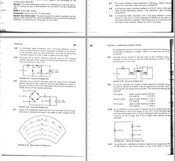
Transcribed Image Text:a magnetic field developed by the
current being measured.
Rectify: To convert alternating current to a unidirectional current by remov-
ing or inverting the part of the waveform on one side of the zero-amplitude
axis.
RMS v: Root-mean-square.
Sinusoidal: Having the form of a sine wave.
Square-law meter scale: The scale required for a meter movement, such as
the iron-vane movement, for which the repelling force, and hence the pointer.
deflection, is proportional to the square of the current.
PROBLEMS
3-4
3-5
3-6
3-7
81
A d'Arsonval meter movement with a full-scale deflection current.
rating of 200 μA and an internal resistance of 500 2 is to be used in
an ac voltmeter using full-wave rectification. Calculate the value of the
multiplier resistor for a 50-V peak-to-peak sine-wave range.
Calculate the ac and dc sensitivity and the value of the multiplier
resistor required to limit current to the full-scale deflection current in
the circuit shown in Fig. 3-23.
E- 20 V
www
R₂
E = 20 V
R-3000
Ro1 = 300 2 R250 2
FIGURE 3-23 Circuit for Problem 3-5.
Calculate the ac and dc sensitivity and the value of the multiplier
resistor required to limit current to the full-scale deflection current in
the circuit shown in Fig. 3-24. All diodes have a forward resistance of
3002 and an infinite reverse resistance.
R250 2
10
FIGURE 3-24 Circuit for Problem 3-6.
Figure 3-25 represents a meter face for an ac voltmeter with full-wave
rectification. Compute the values of the peak-to-peak voltage and the
Es 25
1 MA
-2502
Epp
FIGURE 3-25 Meter scale for Problem 3-7.
½-1 MA
8-250 12
82
1
1
3-1
3-2
The current through a meter movement is 150 μApask. What is the do
value if the instrument uses half-wave rectification?
A d'Arsonval meter movement deflects to 0.8 mA. What is the peak)
value of the alternating current if the instrument uses full-wave.
rectification?
3-3 A d'Arsonval meter movement with a full-scale deflection current
rating of 1 mA and an internal resistance of 500 2 is to be used in a
half-wave rectifier ac voltmeter. Calculate the ac and de sensitivity and
the value of the multiplier resistor for a 30-V rms range.
3-8
CHAPTER 3 ALTERNATING-CURRENT METERS
dc voltage and current for the rms voltages shown if the de sensitivity
of the meter movement is 10 k2/V. Sketch the meter face and fill in
the blanks..
Calculate the dc sensitivity and the value of the multiplier resistor
required to limit current to the full-scale deflection current in the
circuit shown in Fig. 3-26.
E 10 V
eee
R = 0.5
18-20 V
p
FIGURE 3-26 Circuit for Problem 3-8.
3-9 An rms ac voltmeter and a peak-to-peak-reading ac voltmeter are to
be used to determine whether three ac signals are sinusoidal. Deter-
mine whether the signals are sinusoidal if the following readings are
obtained
First signal
Second signal
Third signal
50 mA, R-10
R-0.50
peak-to-peak reading = 35.26 V
rms reading
- 12.00 V
peak-to-peak reading-11.31 V
rms reading.
= 4.00 V
peak-to-peak reading = 25.00 V
rms reading
-8.83 V
3-10 An ac voltmeter is to be used to measure the rms voltage across the
15-k resistor in the circuit shown in Fig. 3-27. If the voltmeter uses"
half-wave rectification and a 100-A d'Arsonval meter movement, if it
is set on its 10-V range, and if R-1.5 k2, what reading will be
obtained?
R₁-25 kn
R₂-15 k
FIGURE 3-27 Circuit for Problem 3-10.
3-11 Two different ac voltmeters are used to measure the voltage across the
22-k2 resistor in the circuit shown in Fig. 3-28. Meter A has ac
Expert Solution
This question has been solved!
Explore an expertly crafted, step-by-step solution for a thorough understanding of key concepts.
Step by stepSolved in 4 steps

Knowledge Booster
Learn more about
Need a deep-dive on the concept behind this application? Look no further. Learn more about this topic, electrical-engineering and related others by exploring similar questions and additional content below.Similar questions
- Question in the attachmentarrow_forwardBased upon the following assumptions: V1 = 13V, V2 = 19V, R1 = 0.9kQ, R2 = 9300, R3 = 3kQ, R4 = 3.4kQ, R5 = 1.2k2. If R5 is the load resistor find VTH Answer in volts with 3 significant digits, only enter the number, don't enter the units. V1 V2arrow_forwardwhat could cause variation in the sum of voltages?arrow_forward
arrow_back_ios
arrow_forward_ios
Recommended textbooks for you
 Introductory Circuit Analysis (13th Edition)Electrical EngineeringISBN:9780133923605Author:Robert L. BoylestadPublisher:PEARSON
 Delmar's Standard Textbook Of ElectricityElectrical EngineeringISBN:9781337900348Author:Stephen L. HermanPublisher:Cengage Learning
 Programmable Logic ControllersElectrical EngineeringISBN:9780073373843Author:Frank D. PetruzellaPublisher:McGraw-Hill Education
 Fundamentals of Electric CircuitsElectrical EngineeringISBN:9780078028229Author:Charles K Alexander, Matthew SadikuPublisher:McGraw-Hill Education
 Electric Circuits. (11th Edition)Electrical EngineeringISBN:9780134746968Author:James W. Nilsson, Susan RiedelPublisher:PEARSON
 Engineering ElectromagneticsElectrical EngineeringISBN:9780078028151Author:Hayt, William H. (william Hart), Jr, BUCK, John A.Publisher:Mcgraw-hill Education,

Introductory Circuit Analysis (13th Edition)
Electrical Engineering
ISBN:9780133923605
Author:Robert L. Boylestad
Publisher:PEARSON

Delmar's Standard Textbook Of Electricity
Electrical Engineering
ISBN:9781337900348
Author:Stephen L. Herman
Publisher:Cengage Learning

Programmable Logic Controllers
Electrical Engineering
ISBN:9780073373843
Author:Frank D. Petruzella
Publisher:McGraw-Hill Education

Fundamentals of Electric Circuits
Electrical Engineering
ISBN:9780078028229
Author:Charles K Alexander, Matthew Sadiku
Publisher:McGraw-Hill Education

Electric Circuits. (11th Edition)
Electrical Engineering
ISBN:9780134746968
Author:James W. Nilsson, Susan Riedel
Publisher:PEARSON

Engineering Electromagnetics
Electrical Engineering
ISBN:9780078028151
Author:Hayt, William H. (william Hart), Jr, BUCK, John A.
Publisher:Mcgraw-hill Education,