
Introductory Circuit Analysis (13th Edition)
13th Edition
ISBN: 9780133923605
Author: Robert L. Boylestad
Publisher: PEARSON
expand_more
expand_more
format_list_bulleted
Related questions
Concept explainers
Question
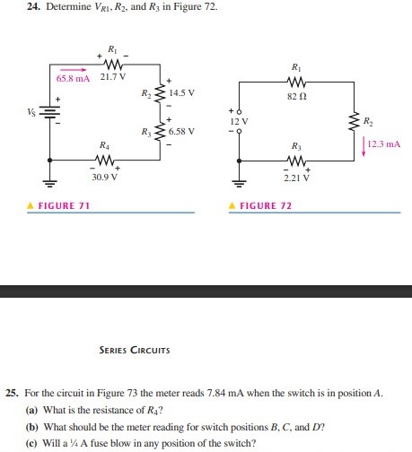

Transcribed Image Text:24. Determine VRI, R2, and R3 in Figure 72.
R
65.8 mA 21.7 V
R2
14.5 V
82 N
Vs
12 V
6.58 V
R4
R3
12.3 mA
30.9 V
2.21 V
A FIGURE 71
FIGURE 72
SERIES CIRCUITS
25. For the circuit in Figure 73 the meter reads 7.84 mA when the switch is in position A.
(a) What is the resistance of R4?
(b) What should be the meter reading for switch positions B, C, and D?
(c) Will a % A fuse blow in any position of the switch?
Expert Solution
This question has been solved!
Explore an expertly crafted, step-by-step solution for a thorough understanding of key concepts.

This is a popular solution

Trending nowThis is a popular solution!

Step by stepSolved in 2 steps

Knowledge Booster


Learn more about
Need a deep-dive on the concept behind this application? Look no further. Learn more about this topic, electrical-engineering and related others by exploring similar questions and additional content below.Similar questions
- Consider a step down converter supplied by a DC power source of magnitude Vs = 220 V. The switching period is 0.1 ms and the duty cycle k is set to 0.5. The load is an inductive load with R=5 Ohms and L=10 mH. The switch is ideal. The RMS converter current IR is equal to 15.56A. The ripple factor of the input current RFs would be equal to: Select one: a. 0% Ob. 50% Oc. 100% d. None of thesearrow_forwardbläs 6 Q3: Calculate voltages between points A,D (V1) and between points B,C (V2) before and after closing switch S A 3 B 15V D S 12 Carrow_forward3-Determine the output voltage in Figure 8 for each of the following failure modes: (a) L1 open (b) L2 open (c) R1 open (d) a short across R2 5 V 1 MHz L₁ m 8.0 μΗ L₂ m 4.0 με Figure 8 R₁ ww 100 (2 R₂ 100 Ω R3 56 Ωarrow_forward
arrow_back_ios
arrow_forward_ios
Recommended textbooks for you
- Introductory Circuit Analysis (13th Edition)Electrical EngineeringISBN:9780133923605Author:Robert L. BoylestadPublisher:PEARSON
 Delmar's Standard Textbook Of ElectricityElectrical EngineeringISBN:9781337900348Author:Stephen L. HermanPublisher:Cengage Learning
 Programmable Logic ControllersElectrical EngineeringISBN:9780073373843Author:Frank D. PetruzellaPublisher:McGraw-Hill Education
  Fundamentals of Electric CircuitsElectrical EngineeringISBN:9780078028229Author:Charles K Alexander, Matthew SadikuPublisher:McGraw-Hill Education
 Electric Circuits. (11th Edition)Electrical EngineeringISBN:9780134746968Author:James W. Nilsson, Susan RiedelPublisher:PEARSON
 Engineering ElectromagneticsElectrical EngineeringISBN:9780078028151Author:Hayt, William H. (william Hart), Jr, BUCK, John A.Publisher:Mcgraw-hill Education,
Introductory Circuit Analysis (13th Edition)
Electrical Engineering
ISBN:9780133923605
Author:Robert L. Boylestad
Publisher:PEARSON
Delmar's Standard Textbook Of Electricity
Electrical Engineering
ISBN:9781337900348
Author:Stephen L. Herman
Publisher:Cengage Learning
Programmable Logic Controllers
Electrical Engineering
ISBN:9780073373843
Author:Frank D. Petruzella
Publisher:McGraw-Hill Education
Fundamentals of Electric Circuits
Electrical Engineering
ISBN:9780078028229
Author:Charles K Alexander, Matthew Sadiku
Publisher:McGraw-Hill Education
Electric Circuits. (11th Edition)
Electrical Engineering
ISBN:9780134746968
Author:James W. Nilsson, Susan Riedel
Publisher:PEARSON
Engineering Electromagnetics
Electrical Engineering
ISBN:9780078028151
Author:Hayt, William H. (william Hart), Jr, BUCK, John A.
Publisher:Mcgraw-hill Education,