2. For each circuit, find the currents through each element, as well as the diode voltage. Express these answers to three decimal places in V or mA, and use the exponential model for the diode, Is = 10-15 A. 10V
Q: or bele inches, set 1.1X=66 and solve for x to get their oric 14. At some point in the season, the…
A: 14. The winning percentage of the Trailblazers team in a basketball tournament at some point is 60…
Q: Determine the power consumed by resistor R₂, given: E=240 V, R = 47 22, R₂ = 39 22, and R₂ = 33 02…
A:
Q: Exercise 1i solve for V of all Rs and solve for I of all Rs
A: In the given circuit the value of the voltage across the resistors and the current through the…
Q: 2) Answer the following problems a), b), c) & d) using the circuit shown below. a) t=0 50 Ω www شه…
A:
Q: how did this happen?
A: Given:an expression,we are required to prove:
Q: HI H 0.4(1 10k > 200u 1000u (a) Buck Converter Fig.1 Vo im 1. In a buck converter, L=200 µH,C=1000μF…
A:
Q: Determine the current i(t) for t>0 of the inductor in the circuit. Consider zero initial conditions.…
A: In the given questions we need to calculate the current flow through the inductor.
Q: What is the current flowing in the resistor network shown below? Given: Vt = 12 Volts, R1 = 12 k…
A:
Q: Shockley voltage of the p-n junction and is defined by ↓ V₁ = kT 9 V↓ where ↓ k is Boltzmann T is…
A: A diode is a semiconductor device that allows current to flow in one direction only. It has two…
Q: What is the voltage at the terminals of the practical voltage source? (symbolically) O Vpt O Vpt O…
A: In the given questions we need to calculate the voltage across the practical voltage source.
Q: plot the transfer characteristics + V₁ | R W ww DZ Z2 VO
A: Given:a circuit, we need to plot transfer characteristic of the above circuit.
Q: What is the equivalent resistance of the combination shown?
A: In this question, we need to determine the equivalent resistance. We solve this problem using the…
Q: please do part a, b ,c. Wave shaping.
A: we need to plot input and output waveforms for given circuits.
Q: For the circuit shown in the figure, the Thevenin resistance seen by RL is: 8 Α 100 V 8 Ω O a. 6.83…
A:
Q: 3. There are four point charges at each corner of a square of side L. Find the magnitude and…
A: There are four point charges are located at each corner of a square of side L as shown below.We…
Q: Analyse the circuit shown in Fig. 9 and draw the waveform at nodes v², v, and vo. Briefly explain…
A: In the given question we need to explain about the given Astable multivibrator circuit.
Q: Find the total current, total impedance, phase angle and reactive power in the circuit in the…
A:
Q: A) solve h(s) = I_(out)/l_(in) B) solve step response C) solve impulse response Please…
A: Given:a circuit,we need to find:a) transfer function b) step responsec) impulse response
Q: Determine the waveform, theoretical, of the peak output voltage at Resistor L. 120 V rms 5:1 ooooo…
A: Given:a full wave rectifier circuit, we are required to determine the output voltage waveform at…
Q: 3. The figure below shows an RC circuit. (a) If the initial charge in the circuit is Q(0) = 0, show…
A: charge on capacitor ,Q=RC
Q: 2.10 Functions x (t) and h(t) are both rectangular pulses, as shown in Fig. P2.10. Apply graphical…
A: The convolution of two rectangular pulses is equal to the triangular pulse.And the amplitude will…
Q: 1. For the low-pass RC filter, calculate the phase and magnitude of the transfer function at…
A: Given data:Low pass RC filter,Frequencies 20,50,100,200,500,1000,1500 HZ,R=50 kC=0.02 Asked to find…
Q: 28. A circuit with four light-emitting diodes (LEDs) P, Q, R and S is shown below. Two LEDs are lit…
A: According to the question, we need to discuss the basic concept of LED on the operation of pn…
Q: A signal is defined x(t) = 6 cos (w₂1 - π —— 3 +2 sin(at)-2 cos(at) Using phasor concepts, express…
A:
Q: above, calculite (a) i, and Vo (b) the power dissipated in the 60 resistor (e) the power developed…
A: In the given circuit the value of unknown voltage and current needs to be calculated. The power…
Q: VHF loop antenna used to receive weather maps from satellites has an mpedance of 10002 at 137MHz.…
A:
Q: Four capacitors are arranged in a circuit as shown in the figure. C₁ C₂ What is the charge Q3 on…
A: In this question, we need to determine the equivalent capacitance, charge on capacitor C3 ,…
Q: Determine the equivalent resistance (in Ohms) in the circuit schematic shown. The resistors have…
A:
Q: ikwot (b) Let x(t) Σ Xkeiku be a p-periodic signal. k=-∞ (i) Determine the Fourier coefficients of…
A: Given:a periodic signal, we are required to find:i) Fourier series coefficients of ii) Fourier…
Q: Which of the following statements regarding turbine control are true? Select one or more: a. The yaw…
A: Given:Statements regarding turbine control:a) The yaw control ensures that the turbine is constantly…
Q: Coaxial cable is used in applications requiring the propagation of high-frequency signal. Such cable…
A: According to the question, we need to calculate the capacitance of the RG-59/U coaxial cable.Inner…
Q: 2. Designing a Logic Circuit with minimized NAND Gates Only: Design a logic circuit with inputs from…
A: we are required to design a logic circuit using minimized NAND gates only.
Q: Given the plot of V. (t), i.e., the voltage on a capacitor, which is the correct expression for Ic…
A:
Q: . Consider the periodic voltage v.(t) and the circuit shown below. Use amplitude-phase Fourier…
A: Fourier series is a mathematical tool used to represent periodic functions as the sum of sinusoidal…
Q: A straight thin rod of length L has a uniform charge per length and its total charge is Q. Find the…
A: In the given question we need to calculate the voltage at point p.
Q: 4.47 A cylinder-shaped carbon resistor is 8 cm in length and its circular cross section has a…
A: Given data,Length of the carbon resistor l = 8 cm,diameter d = 1 mm,Asked to,Determine the…
Q: 1. wwww R₁ wwww R₂ www Ra P Watts Volts Amps Ohms Circuit Calculation Table Supply PT= E₁ = 14.4 IT…
A:
Q: A circuit is shown in (Figure 1), with R 1 = 10 \Omega, R2 = 10 \Omega, R 3 = 10 \Omega, R4 = 16…
A: In this question, we need to determine the current flow in the resistance R4 as shown in the…
Q: Determine the Laplace transform of these functions:
A: In this question, we need to determine the Laplace transform of these functions. We solve this…
Q: V1 -8V tilt R5 1kQ R1 1kQ From your class notes: Show all work for full credit!! R4 ww 3ΚΩ www R2…
A: In this question, we need to determine the voltages across the each resistances. Prove that power…
Q: A generation station has maximum demand of 10,000KW, the daily demand as following, calculate the…
A: "Since you have asked multiple questions, we will solve the first question for you. If you want any…
Q: the transfer function  (s). (dB) |^v | the magnitude and phase Bode plots shown below. Find an…
A:
Q: rEr= 5/(Permitivity of free space Eo) *( integral from 0 to r )*r^2*e^(-r) dr .
A:
Q: 11.16 In a balance three-phase system, the source is a balanced Y with an abc phase sequence and a…
A:
Q: In the circuit below "I" is a DC current, and vs is a sinusoidal signal. Given the diode has VD=…
A: Please find the below answer in which have explained clearly by step by step. So, please give good…
Q: A mixed circuit is shown in the figure below. For each resistor, its voltage and current, as well as…
A: Given circuit,Asked to find the current and voltage in each resistor.And Total resistance seen by…
Q: Needs Complete solution with 100 % accuracy.
A: The objective of this question is to calculate the reading of a wattmeter connected in a 3-phase,…
Q: V₂ 1 ΚΩ www 31 ΚΩ 1 ΚΩ M 20 V - 20 V Ι V₁ 1ΚΩ Vo ww Ix 1 ΚΩ 20 V - 20 V I 2 kΩ 1kΩ 31 ΚΩ Calculate…
A: VS=1 VAV=104Given circuit: -
Q: Find the Thevenin equivalent of this network. 12020⁰ -j4 k = 0.5 j5 j20 j2 4+j6 000 Vm=? ZTE = ?
A: Thevenin's Theorem is a fundamental concept in electrical engineering used to simplify complex…
Q: rove the identity of each of the following Boolean equations using algebraic anipulation: (a) XỸ +ÝZ…
A: Boolean algebra is a branch of mathematics and a formal system used in computer science and digital…
Needs Complete typed solution with 100 % accuracy.
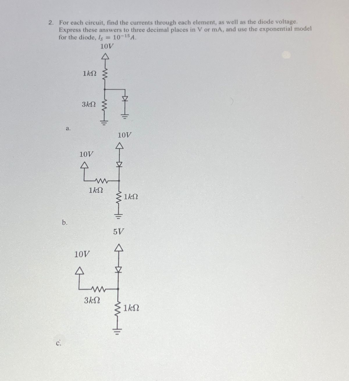
Trending now
This is a popular solution!
Step by step
Solved in 4 steps with 3 images
- How is a solid-state diode tested? Explain.Assuming an ideal diode model for all the diodes in the circuit below, Calculate the voltage across and current flow through each diode R1 9k0 IN1199C 01 18k IN1199C D3 IN1199C 12 1k0 R4 SkO 1- V 11 mA 0.5 mA 0.1 A OuO 9:.0 A docs.google.com * ZAIN IQ l. Q3/B: Assume an ideal diode model for all the diodes in the circuit below. calculate voltages and currents through D1 and D2 9kQ 1N1199C R2 D1 18KQ 1N1199C D3 1N1199C V2 =12 V R3 1kQ R4 5kQ 1.22 V 11 mA 0.5 A O VD1 ID1 VD2 ID2 صفحة 4 من 6
- I ln. l. . :D docs.google.com/forms/d/e/1l Diode clippers are wave-shaping circuits in that they are not used to prevent signal voltage from going above or below certain * .levels TO F like that of the clipper, the shape of the .input signals of a clamper is changed F The clamping circuit clamps or shift the * .input sinusoidal signal up or down FO IIAssuming an ideal diode model for all the diodes in the circuit below, chose the correct state (bias) for each diode. 9kO IN1199C R2 01 18KO IN11990 D3 IN1199C R3 V2 12 V R4 5kQAssuming an ideal diode model for all the diodes in the circuit below, Calculate the voltage across and current flow through each diode 9kO 1N1199C R2 01 18kO IN1199C V2 12 V- R3 1kO D3 1N1199C R4 5kQ
- _mA. No If a Si diode at room temperature (25°) has a leakage current Is = 46 nA, k = 5,800, and V₁ = 0.65 V, The diode current is need for a solution. Just write your numeric answer in the space provided. Round off your answer to 2 decimal places. Add your answer Short answer. What is the greatest threat to a diode? Use the editor to format your answer Short answer. What type of bias makes a diode act as a closed switch? Use the editor to format your answerJump to i) If the input is 10V sine wave, plot the output voltage. The Zener voltage of D1, D2 and D3 are 3.2 V, 3V and 2.8V, respectively. ( R1 ww D1 D2 Vout D3 (ii)Find the output voltage waveform if Vin-150 V and N=3. Assume non ideal diode. D1 D4 D2 RL V out urns Ratio is N:1. lll2. Draw the input and output waveform for the following clipper circuits if input signal is triangle wave of 10V peak to peak (5V zero to peak) and 1kHz. Diodes are IDEAL diode. 1 V1 5Vpk 1kHz 0° 0 D1 2 V2 till 2V 3 R1 >1kQ ~ 1 V1 5Vpk 1kHz 0° R1 1kQ 0 D1 V2 -2V 2 4 D2 V3 2V R2 100kQ2
- Assuming an ideal diode model for all the diodes in the circuit below, chose the correct state (bias) for each diode. R1 ww 9kQ 1N1199C R2 D1 18kQ 1N1199C V2 12 V R3 1kQ D3 1N1199C R4 D3: On (Forward Bais) D3: Off (Reverse Bais)A clipper circuit based on diodes are simple way to modify waveform in mechatronics. Assume that the two diodes shown in the circuit below are ideal diodes. If the input voltage in the circuit is a 1 kHz sinusoid with peak amplitude of 8V, sketch the Va.. (t) 10 kO 8V 10 kO Vin Vin(t) D2 Vout(t) RL Ims D1 6V -8V 4V Page | 1Draw output waveform for the following circuit. Suppose input is a pure square wave with a positive half at 10 V and negative half at -10 V for ideal diodes. D1 D2 220 R3 R1 1k R2 1k