Power System Analysis and Design (MindTap Course List)
6th Edition
ISBN: 9781305632134
Author: J. Duncan Glover, Thomas Overbye, Mulukutla S. Sarma
Publisher: Cengage Learning
expand_more
expand_more
format_list_bulleted
Concept explainers
Question

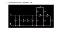
Transcribed Image Text:2. Find the total resistance at terminal A-B
36
ww
63
43
А
64
36
ww
36
45
36
10
76
63
86
26
ww
ww
ww
B
Expert Solution
This question has been solved!
Explore an expertly crafted, step-by-step solution for a thorough understanding of key concepts.
Step by stepSolved in 3 steps with 2 images

Knowledge Booster
Learn more about
Need a deep-dive on the concept behind this application? Look no further. Learn more about this topic, electrical-engineering and related others by exploring similar questions and additional content below.Similar questions
- An abrupt silicon pn junction at zero bias has dopant concentrations of Nd = 1 X 1017 cm-3 cm³ and Na and N₂ = 5 X 1016 cm¯³ at T = 300K. Determine the peak electric field for this junction for a reverse voltage of 2 V. Emax = 3.88 X 10⁵ V/cm Emax = 1.35 X 10⁵ V/cm Emax 1.70 X 10⁵ V/cm O Emax = 3.21 X 10⁵ V/cm =arrow_forwardA thermal bimorph can be used as an actuator. In this problem, you will use the principles of “crayon engineering” to design a process and mask set that will produce a silicon‐based cantilever thermal bimorph with an integrated heater and an underlying hole structure as shown below. (Silicon‐based means that the final structure is made of silicon, plus oxide, nitride, and metal as needed. You don’t have to use a plain silicon wafer, but you can’t make the whole thing out of a completely different material like metal or SU8.) A description of the structure follows; a top view is shown in Figure 2. Where a dimension is not specified (like the lateral extent of the hole), you are free to choose a process that you think makes sense. This may turn out to be an economic trade‐off (for example, cost of processes vs. wasted space on the wafer). Cantilever composition: The cantilever includes a silicon structure, a metal layer on top of that (you can choose either Al or Au), an integrated…arrow_forwardQ5. For the following center tapped transformer, show the waveform across each half of the secondary winding and across Ri, when a 100 V peak sine wave is applied to the primarywinding. What is the PIV rating must the diode have? (Use constant voltage drop model for the Silicon diode) IN4001 Ry OV 10k) D IN4001arrow_forward
- Show me step by step how to do this designarrow_forwardReconsider Problem 3.29. If Va,VbandVc are a negative-sequence set, how would the voltage and current relationships change? (a) If C1 is the complex positive-sequence voltage gain in Problem 3.29 and (b) if C2 is the negative sequence complex voltage gain, express the relationship between C1andC2arrow_forwardI need the correct expert solution with explanation of the steps of the solution and the abbreviations, please.arrow_forward
- question in photo pleasearrow_forwardC'uk Converter Design A C'uk converter has an input of 12 V and is to have an output of - 24 V supplying a 60 W load. Select the duty ratio, the switching frequency, the inductor sizes such that the change in inductor currents is no more than 12 percent of the average inductor current, the output ripple voltage is no more than 1.5 percent, and the ripple voltage across C1 is no more than 3 percent.arrow_forwardYou are required to design a two types of load cells. A Cantilever beam load cell and a Hollow cylinder load cell. What equations would you use to measure strain and voltage.arrow_forward
- What are 8 degenerate 2 level forms in digital electronics? How can 2 level forms be used to extend the number of inputs to gate?arrow_forwardnot use ai pleasearrow_forwardI need some help with this problem. I need to create a power supply from 110v 60hz to regulated an output between 6 and 9 v. the image is the desire circuit to acomplish the possible solution. The resistor after the bridge rectifier will work as a surge protector or current limiter for the zener diode. the other is the Load resistor. I need some sort of calculations to prove the specific values for the components to operate according to the specs that I already explain. I know the capacitor will smooth the ripple voltage etc... but I need some guidance to get actual valuesarrow_forward
arrow_back_ios
SEE MORE QUESTIONS
arrow_forward_ios
Recommended textbooks for you
 Power System Analysis and Design (MindTap Course ...Electrical EngineeringISBN:9781305632134Author:J. Duncan Glover, Thomas Overbye, Mulukutla S. SarmaPublisher:Cengage Learning
 Delmar's Standard Textbook Of ElectricityElectrical EngineeringISBN:9781337900348Author:Stephen L. HermanPublisher:Cengage Learning

Power System Analysis and Design (MindTap Course ...
Electrical Engineering
ISBN:9781305632134
Author:J. Duncan Glover, Thomas Overbye, Mulukutla S. Sarma
Publisher:Cengage Learning

Delmar's Standard Textbook Of Electricity
Electrical Engineering
ISBN:9781337900348
Author:Stephen L. Herman
Publisher:Cengage Learning