
Elements Of Electromagnetics
7th Edition
ISBN: 9780190698614
Author: Sadiku, Matthew N. O.
Publisher: Oxford University Press
expand_more
expand_more
format_list_bulleted
Question
Please answer all parts
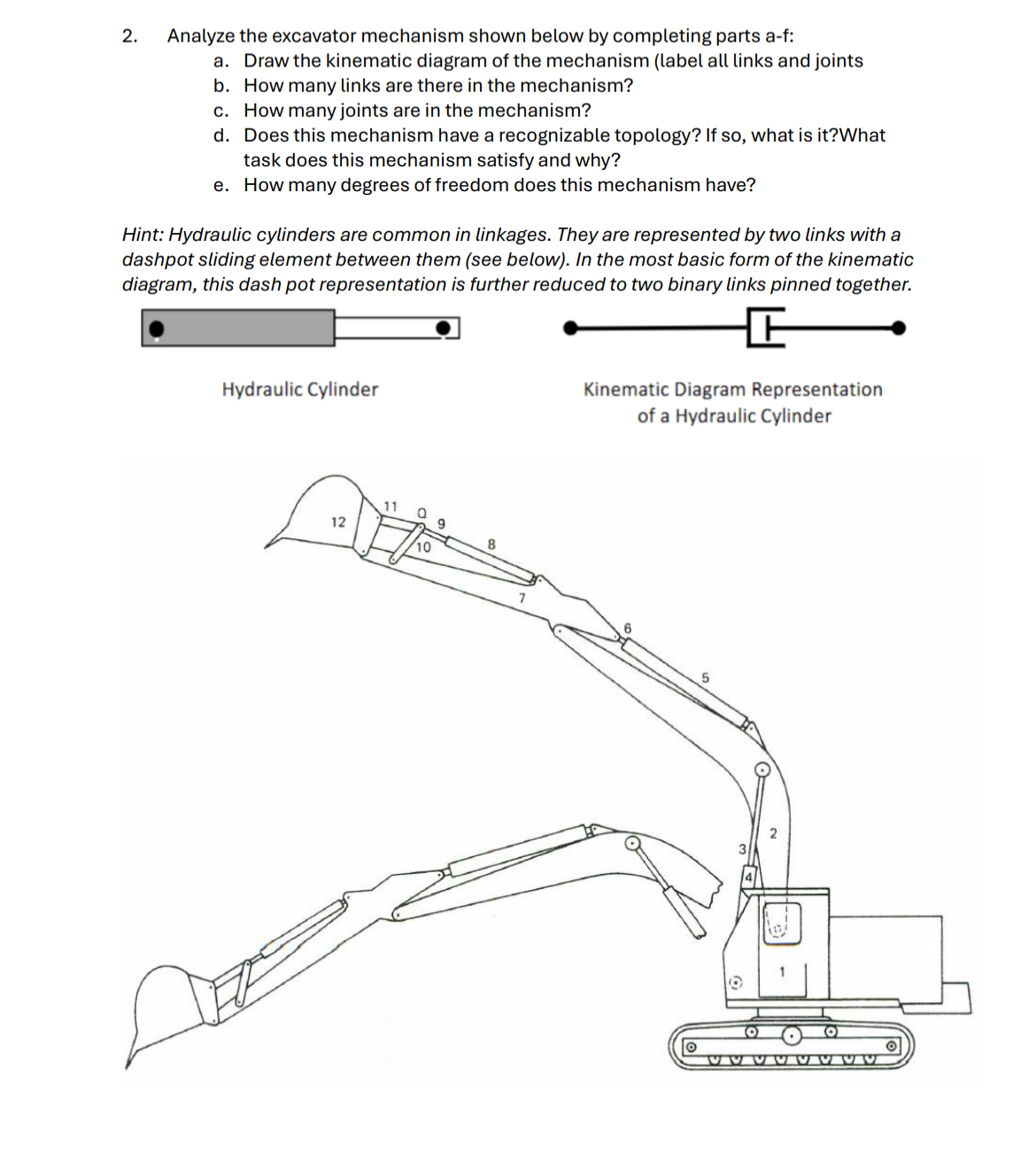

Transcribed Image Text:2.
Analyze the excavator mechanism shown below by completing parts a-f:
a. Draw the kinematic diagram of the mechanism (label all links and joints
b. How many links are there in the mechanism?
c. How many joints are in the mechanism?
d. Does this mechanism have a recognizable topology? If so, what is it?What
task does this mechanism satisfy and why?
e. How many degrees of freedom does this mechanism have?
Hint: Hydraulic cylinders are common in linkages. They are represented by two links with a
dashpot sliding element between them (see below). In the most basic form of the kinematic
diagram, this dash pot representation is further reduced to two binary links pinned together.
Hydraulic Cylinder
11
0
9
8
12
10
Kinematic Diagram Representation
of a Hydraulic Cylinder
6
5
O
VVVVVVVV
Expert Solution
This question has been solved!
Explore an expertly crafted, step-by-step solution for a thorough understanding of key concepts.

Step by stepSolved in 2 steps with 6 images

Knowledge Booster

Similar questions
- Solve only no 1 calculations,the one with diagram,I need handwritten expert solutionsarrow_forwardFor the manipulator shown in the figure below, answer the following; P 1) How many joints does this manipulator have, and what types? 2) What are the measurements needed to analyse the mechanism? 3) Assign appropriate frames for D.-H. analysis from frame {0} to frame {P}? (redraw the manipulator on the answer book or do it on the questions sheet) 4) Is this a 2D problem or a 3D problem, and explain why?arrow_forwardb) You are given a set of six links. The lengths of the links are as follows: 6.3cm, 9.1cm,12.4cm,15.6cm,20cm,40.2cmSketch a crank-rocker mechanism you can realize using a selection of four links from the set.arrow_forward
- 500 mm B B2 A2 O2, 61.9292 X-line The slider-crank mechanism has a stroke of 500 mm. The required advance-to-return ratio is 1.80. The crank angle during the advance stroke (a), crank angle during the return stroke (B), crank link length (r2), and coupler length (ra) is. (See Theory of Machines and Mechanism, 5th Edition, Problem 1.31) (NOTE: Use the angle for the X-Line as shown) (a) a=231.43°, B=128.57°, r2-301.872 mm, r3=412.751 mm (b) a=128.57°, B=231.43°, r2=223.875 mm, r3=340.409 mm (c) a=231.43°, B=128.57°, r2-223.875 mm, r3-340.409 mm (d) a=128.57°, B=231.43°, r2=191.751 mm, r3-387.233 mmarrow_forwardPlease help me answer this, I just need the interpretation of this or how to draw this given the instructions. Pleasee, show me how you draw this, thank you in advance!arrow_forward|design a simple piston-like crank-slider mechanism that looks similar to the Figure 4 (not to scale). The centre of the crank and the slider are aligned vertically to each other. It has already been determined that the crank radius (O2A) must be 25mm, while the slider block is in a square shape of 20 mm by 20 mm. The highest position of the slider (Hmax), which is the furthest vertical distance of the slider from the centre of the crank, must be 92 mm. Based on the given design parameters, your task is to determine the suitable couple length (AB) and the lowest position of the slider (Hmin). Your superior has asked you to present the results graphically. 20 Slider 10 20 H Crank O2 Figure 4arrow_forward
- The figures below show a mechanism for a crushing machine with a kinematic diagram. The aim is to determine the number of li joints , half joints and DOF (Mobility) of the system, in addition, the drawing of the kinematic diagram must be checked. + 230 mm 230 mm 60 mm 25° Crank 180 mm 250 mm 320 mm Crushing ram 250 mm 180 mm 250 mmarrow_forwardvery urgent i need her solving all part pls quickk (mechanical system)arrow_forwardPlease veryyy urgent pls quickk (mechanical system) using rulesarrow_forward
arrow_back_ios
SEE MORE QUESTIONS
arrow_forward_ios
Recommended textbooks for you
- Elements Of ElectromagneticsMechanical EngineeringISBN:9780190698614Author:Sadiku, Matthew N. O.Publisher:Oxford University Press
 Mechanics of Materials (10th Edition)Mechanical EngineeringISBN:9780134319650Author:Russell C. HibbelerPublisher:PEARSON
 Thermodynamics: An Engineering ApproachMechanical EngineeringISBN:9781259822674Author:Yunus A. Cengel Dr., Michael A. BolesPublisher:McGraw-Hill Education
  Control Systems EngineeringMechanical EngineeringISBN:9781118170519Author:Norman S. NisePublisher:WILEY
 Mechanics of Materials (MindTap Course List)Mechanical EngineeringISBN:9781337093347Author:Barry J. Goodno, James M. GerePublisher:Cengage Learning
 Engineering Mechanics: StaticsMechanical EngineeringISBN:9781118807330Author:James L. Meriam, L. G. Kraige, J. N. BoltonPublisher:WILEY
Elements Of Electromagnetics
Mechanical Engineering
ISBN:9780190698614
Author:Sadiku, Matthew N. O.
Publisher:Oxford University Press
Mechanics of Materials (10th Edition)
Mechanical Engineering
ISBN:9780134319650
Author:Russell C. Hibbeler
Publisher:PEARSON
Thermodynamics: An Engineering Approach
Mechanical Engineering
ISBN:9781259822674
Author:Yunus A. Cengel Dr., Michael A. Boles
Publisher:McGraw-Hill Education
Control Systems Engineering
Mechanical Engineering
ISBN:9781118170519
Author:Norman S. Nise
Publisher:WILEY
Mechanics of Materials (MindTap Course List)
Mechanical Engineering
ISBN:9781337093347
Author:Barry J. Goodno, James M. Gere
Publisher:Cengage Learning
Engineering Mechanics: Statics
Mechanical Engineering
ISBN:9781118807330
Author:James L. Meriam, L. G. Kraige, J. N. Bolton
Publisher:WILEY